AI App UI Design

AI App UI Design — independent reviews, comparisons, pricing and step-by-step guides on Aizhi.

  • ActivTrak

    ActivTrak

    ActivTrak is an American company that produces workforce analytics and productivity software. The company was founded in 2009 by Birch Grove Software and is headquartered in Austin, Texas. The company has raised US$77.5 million in funding and is backed by Sapphire Ventures and Elsewhere Partners. == History == ActivTrak was founded in 2009 by Herb Axilrod and Anton Seidler in Dallas, Texas. ActivTrak's first on-demand software product launched in 2012, and the workforce analytics platform launched in 2015. It uses data sourced from more than 9,500 customers and 900,000 users. In 2019, ActivTrak raised $20 million in a Series A round of funding with Elsewhere Partners, a growth-stage venture capital firm that principally invests in B2B startups. Rita Selvaggi assumed the role of CEO. In 2020, ActivTrak raised $50M in a Series B round of funding with Sapphire Ventures and Elsewhere Partners. The company also introduced the ActivTrak Productivity Lab, an online resource about workforce productivity research, industry benchmark data, and best practices. == Product == ActivTrak is a workforce analytics and productivity platform that uses reports, dashboards, and data analysis. The platform uses machine learning (AI) to collect and analyze user activity data and produce reports about workforce productivity. The software runs on Microsoft Windows, Mac, Chrome, Terminal Services, and VDI. It includes the ActivTrak Agent, which runs in the background and collects data. It responds to user activity, sensing mouse and keyboard movement in the active window(s) of the user's device. This data is collected and stored in a database that aggregates the data based on the user's request. ActivTrak does not utilize keystroke logging, content scraping, camera access, video recording or mobile device monitoring. The database leverages data analytics to generate account and team benchmarks, and identify productivity patterns and outliers. == Awards == Built In, 100 Best Midsize Places to Work in Austin, 2025 G2, Winter: Best Estimated ROI, High Performer, Best Relationship, Best Support, Users Most Likely to Recommend, Easiest Setup, Easiest Admin, Best Meets Requirements, Users Love Us, 2025 TrustRadius, Buyer’s Choice, 2025 Deloitte Technology Fast 500, No. 468 Fastest-Growing Company, 2024 Product Marketing Alliance, AI Marketing Innovation, 2024 Fortune Best Workplaces in Technology™, 2024 Inc. 5000, No. 2335 of America’s Fastest-Growing Private Companies, 2024 Fortune Best Workplaces in Texas™, 2024 Reworked IMPACT Gold Award: Most Innovative Workplace Productivity Solution, 2024 TrustRadius, Most Loved, 2024 Great Place To Work-Certified™, 2024 Inc. 5000 Regionals: Southwest, 2024 Brandon Hall Group, Best Advance in HR Predictive Analytics Technology, 2024

    Read more →
  • Error-driven learning

    Error-driven learning

    In reinforcement learning, error-driven learning is a method for adjusting a model's (intelligent agent's) parameters based on the difference between its output results and the ground truth. These models stand out as they depend on environmental feedback, rather than explicit labels or categories. They are based on the idea that language acquisition involves the minimization of the prediction error (MPSE). By leveraging these prediction errors, the models consistently refine expectations and decrease computational complexity. Typically, these algorithms are operated by the GeneRec algorithm. Error-driven learning has widespread applications in cognitive sciences and computer vision. These methods have also found successful application in natural language processing (NLP), including areas like part-of-speech tagging, parsing, named entity recognition (NER), machine translation (MT), speech recognition (SR), and dialogue systems. == Formal Definition == Error-driven learning models are ones that rely on the feedback of prediction errors to adjust the expectations or parameters of a model. The key components of error-driven learning include the following: A set S {\displaystyle S} of states representing the different situations that the learner can encounter. A set A {\displaystyle A} of actions that the learner can take in each state. A prediction function P ( s , a ) {\displaystyle P(s,a)} that gives the learner's current prediction of the outcome of taking action a {\displaystyle a} in state s {\displaystyle s} . An error function E ( o , p ) {\displaystyle E(o,p)} that compares the actual outcome o {\displaystyle o} with the prediction p {\displaystyle p} and produces an error value. An update rule U ( p , e ) {\displaystyle U(p,e)} that adjusts the prediction p {\displaystyle p} in light of the error e {\displaystyle e} . == Algorithms == Error-driven learning algorithms refer to a category of reinforcement learning algorithms that leverage the disparity between the real output and the expected output of a system to regulate the system's parameters. Typically applied in supervised learning, these algorithms are provided with a collection of input-output pairs to facilitate the process of generalization. The widely utilized error backpropagation learning algorithm is known as GeneRec, a generalized recirculation algorithm primarily employed for gene prediction in DNA sequences. Many other error-driven learning algorithms are derived from alternative versions of GeneRec. == Applications == === Cognitive science === Simpler error-driven learning models effectively capture complex human cognitive phenomena and anticipate elusive behaviors. They provide a flexible mechanism for modeling the brain's learning process, encompassing perception, attention, memory, and decision-making. By using errors as guiding signals, these algorithms adeptly adapt to changing environmental demands and objectives, capturing statistical regularities and structure. Furthermore, cognitive science has led to the creation of new error-driven learning algorithms that are both biologically acceptable and computationally efficient. These algorithms, including deep belief networks, spiking neural networks, and reservoir computing, follow the principles and constraints of the brain and nervous system. Their primary aim is to capture the emergent properties and dynamics of neural circuits and systems. === Computer vision === Computer vision is a complex task that involves understanding and interpreting visual data, such as images or videos. In the context of error-driven learning, the computer vision model learns from the mistakes it makes during the interpretation process. When an error is encountered, the model updates its internal parameters to avoid making the same mistake in the future. This repeated process of learning from errors helps improve the model's performance over time. For NLP to do well at computer vision, it employs deep learning techniques. This form of computer vision is sometimes called neural computer vision (NCV), since it makes use of neural networks. NCV therefore interprets visual data based on a statistical, trial and error approach and can deal with context and other subtleties of visual data. === Natural Language Processing === ==== Part-of-speech tagging ==== Part-of-speech (POS) tagging is a crucial component in Natural Language Processing (NLP). It helps resolve human language ambiguity at different analysis levels. In addition, its output (tagged data) can be used in various applications of NLP such as information extraction, information retrieval, question Answering, speech eecognition, text-to-speech conversion, partial parsing, and grammar correction. ==== Parsing ==== Parsing in NLP involves breaking down a text into smaller pieces (phrases) based on grammar rules. If a sentence cannot be parsed, it may contain grammatical errors. In the context of error-driven learning, the parser learns from the mistakes it makes during the parsing process. When an error is encountered, the parser updates its internal model to avoid making the same mistake in the future. This iterative process of learning from errors helps improve the parser's performance over time. In conclusion, error-driven learning plays a crucial role in improving the accuracy and efficiency of NLP parsers by allowing them to learn from their mistakes and adapt their internal models accordingly. ==== Named entity recognition (NER) ==== NER is the task of identifying and classifying entities (such as persons, locations, organizations, etc.) in a text. Error-driven learning can help the model learn from its false positives and false negatives and improve its recall and precision on (NER). In the context of error-driven learning, the significance of NER is quite profound. Traditional sequence labeling methods identify nested entities layer by layer. If an error occurs in the recognition of an inner entity, it can lead to incorrect identification of the outer entity, leading to a problem known as error propagation of nested entities. This is where the role of NER becomes crucial in error-driven learning. By accurately recognizing and classifying entities, it can help minimize these errors and improve the overall accuracy of the learning process. Furthermore, deep learning-based NER methods have shown to be more accurate as they are capable of assembling words, enabling them to understand the semantic and syntactic relationship between various words better. ==== Machine translation ==== Machine translation is a complex task that involves converting text from one language to another. In the context of error-driven learning, the machine translation model learns from the mistakes it makes during the translation process. When an error is encountered, the model updates its internal parameters to avoid making the same mistake in the future. This iterative process of learning from errors helps improve the model's performance over time. ==== Speech recognition ==== Speech recognition is a complex task that involves converting spoken language into written text. In the context of error-driven learning, the speech recognition model learns from the mistakes it makes during the recognition process. When an error is encountered, the model updates its internal parameters to avoid making the same mistake in the future. This iterative process of learning from errors helps improve the model's performance over time. ==== Dialogue systems ==== Dialogue systems are a popular NLP task as they have promising real-life applications. They are also complicated tasks since many NLP tasks deserving study are involved. In the context of error-driven learning, the dialogue system learns from the mistakes it makes during the dialogue process. When an error is encountered, the model updates its internal parameters to avoid making the same mistake in the future. This iterative process of learning from errors helps improve the model's performance over time. == Advantages == Error-driven learning has several advantages over other types of machine learning algorithms: They can learn from feedback and correct their mistakes, which makes them adaptive and robust to noise and changes in the data. They can handle large and high-dimensional data sets, as they do not require explicit feature engineering or prior knowledge of the data distribution. They can achieve high accuracy and performance, as they can learn complex and nonlinear relationships between the input and the output. == Limitations == Although error driven learning has its advantages, their algorithms also have the following limitations: They can suffer from overfitting, which means that they memorize the training data and fail to generalize to new and unseen data. This can be mitigated by using regularization techniques, such as adding a penalty term to the loss function, or reducing the complexity of the model. They can be sensitive to the choice of

    Read more →
  • FERET (facial recognition technology)

    FERET (facial recognition technology)

    The Facial Recognition Technology (FERET) program was a government-sponsored project that aimed to create a large, automatic face-recognition system for intelligence, security, and law enforcement purposes. The program began in 1993 under the combined leadership of Dr. Harry Wechsler at George Mason University (GMU) and Dr. Jonathon Phillips at the Army Research Laboratory (ARL) in Adelphi, Maryland and resulted in the development of the Facial Recognition Technology (FERET) database. The goal of the FERET program was to advance the field of face recognition technology by establishing a common database of facial imagery for researchers to use and setting a performance baseline for face-recognition algorithms. Potential areas where this face-recognition technology could be used include: Automated searching of mug books using surveillance photos Controlling access to restricted facilities or equipment Checking the credentials of personnel for background and security clearances Monitoring airports, border crossings, and secure manufacturing facilities for particular individuals Finding and logging multiple appearances of individuals over time in surveillance videos Verifying identities at ATM machines Searching photo ID records for fraud detection The FERET database has been used by more than 460 research groups and is currently managed by the National Institute of Standards and Technology (NIST). By 2017, the FERET database has been used to train artificial intelligence programs and computer vision algorithms to identify and sort faces. == History == The origin of facial recognition technology is largely attributed to Woodrow Wilson Bledsoe and his work in the 1960s, when he developed a system to identify faces from a database of thousands of photographs. The FERET program first began as a way to unify a large body of face-recognition technology research under a standard database. Before the program's inception, most researchers created their own facial imagery database that was attuned to their own specific area of study. These personal databases were small and usually consisted of images from less than 50 individuals. The only notable exceptions were the following: Alex Pentland’s database of around 7500 facial images at the Massachusetts Institute of Technology (MIT) Joseph Wilder's database of around 250 individuals at Rutgers University Christoph von der Malsburg’s database of around 100 facial images at the University of Southern California (USC) The lack of a common database made it difficult to compare the results of face recognition studies in the scientific literature because each report involved different assumptions, scoring methods, and images. Most of the papers that were published did not use images from a common database nor follow a standard testing protocol. As a result, researchers were unable to make informed comparisons between the performances of different face-recognition algorithms. In September 1993, the FERET program was spearheaded by Dr. Harry Wechsler and Dr. Jonathon Phillips under the sponsorship of the U.S. Department of Defense Counterdrug Technology Development Program through DARPA with ARL serving as technical agent. === Phase I === The first facial images for the FERET database were collected from August 1993 to December 1994, a time period known as Phase I. The pictures were initially taken with a 35-mm camera at both GMU and ARL facilities, and the same physical setup was used in each photography session to keep the images consistent. For each individual, the pictures were taken in sets, including two frontal views, a right and left profile, a right and left quarter profile, a right and left half profile, and sometimes at five extra locations. Therefore, a set of images consisted of 5 to 11 images per person. At the end of Phase I, the FERET database had collected 673 sets of images, resulting in over 5000 total images. At the end of Phase I, five organizations were given the opportunity to test their face-recognition algorithm on the newly created FERET database in order to compare how they performed against each other. There five principal investigators were: MIT, led by Alex Pentland Rutgers University, led by Joseph Wilder The Analytic Science Company (TASC), led by Gale Gordon The University of Illinois at Chicago (UIC) and the University of Illinois at Urbana-Champaign, led by Lewis Sadler and Thomas Huang USC, led by Christoph von der Malsburg During this evaluation, three different automatic tests were given to the principal investigators without human intervention: The large gallery test, which served to baseline how algorithms performed against a database when it has not been properly tuned. The false-alarm test, which tested how well the algorithm monitored an airport for suspected terrorists. The rotation test, which measured how well the algorithm performed when the images of an individual in the gallery had different poses compared to those in the probe set. For most of the test trials, the algorithms developed by USC and MIT managed to outperform the other three algorithms for the Phase I evaluation. === Phase II === Phase II began after Phase I, and during this time, the FERET database acquired more sets of facial images. By the start of the Phase II evaluation in March 1995, the database contained 1109 sets of images for a total of 8525 images of 884 individuals. During the second evaluation, the same algorithms from the Phase I evaluation were given a single test. However, the database now contained significantly more duplicate images (463, compared to the previous 60), making the test more challenging. === Phase III === Afterwards, the FERET program entered Phase III where another 456 sets of facial images were added to the database. The Phase III evaluation, which took place in September 1996, aimed to not only gauge the progress of the algorithms since the Phase I assessment but also identify the strengths and weaknesses of each algorithm and determine future objectives for research. By the end of 1996, the FERET database had accumulated a total of 14,126 facial images pertaining to 1199 different individuals as well as 365 duplicate sets of images. As a result of the FERET program, researchers were able to establish a common baseline for comparing different face-recognition algorithms and create a large standard database of facial images that is open for research. In 2003, DARPA released a high-resolution, 24-bit color version of the images in the FERET database (existing reference).

    Read more →
  • Relation network

    Relation network

    A relation network (RN) is an artificial neural network component with a structure that can reason about relations among objects. An example category of such relations is spatial relations (above, below, left, right, in front of, behind). RNs can infer relations, they are data efficient, and they operate on a set of objects without regard to the objects' order. == History == In June 2017, DeepMind announced the first relation network. It claimed that the technology had achieved "superhuman" performance on multiple question-answering problem sets. == Design == RNs constrain the functional form of a neural network to capture the common properties of relational reasoning. These properties are explicitly added to the system, rather than established by learning just as the capacity to reason about spatial, translation-invariant properties is explicitly part of convolutional neural networks (CNN). The data to be considered can be presented as a simple list or as a directed graph whose nodes are objects and whose edges are the pairs of objects whose relationships are to be considered. The RN is a composite function: R N ( O ) = f ϕ ( ∑ i , j g θ ( o i , o j , q ) ) , {\displaystyle RN\left(O\right)=f_{\phi }\left(\sum _{i,j}g_{\theta }\left(o_{i},o_{j},q\right)\right),} where the input is a set of "objects" O = { o 1 , o 2 , . . . , o n } , o i ∈ R m {\displaystyle O=\left\lbrace o_{1},o_{2},...,o_{n}\right\rbrace ,o_{i}\in \mathbb {R} ^{m}} is the ith object, and fφ and gθ are functions with parameters φ and θ, respectively and q is the question. fφ and gθ are multilayer perceptrons, while the 2 parameters are learnable synaptic weights. RNs are differentiable. The output of gθ is a "relation"; therefore, the role of gθ is to infer any ways in which two objects are related. Image (128x128 pixel) processing is done with a 4-layer CNN. Outputs from the CNN are treated as the objects for relation analysis, without regard for what those "objects" explicitly represent. Questions were processed with a long short-term memory network.

    Read more →
  • Bottlenose (company)

    Bottlenose (company)

    Bottlenose.com, also known as Bottlenose, is an enterprise trend intelligence company that analyzes big data and business data to detect trends for brands. It helps Fortune 500 enterprises discover, and track emerging trends that affect their brands. The company uses natural language processing, sentiment analysis, statistical algorithms, data mining, and machine learning heuristics to determine trends, and has a search engine that gathers information from social networks. KPMG Capital has invested a "substantial amount" in the company. Bottlenose processed 72 billion messages per day, in real-time, from across social and broadcast media, as of December 2014. == History == The company is based in Los Angeles, CA. Bottlenose is a real-time trend intelligence tool that measures social media campaigns and trends. The company also provides a free version of its Sonar tool that shows real-time trends across social media. In October 2012, the company received $1 million of funding from ff Venture Capital and Prosper Capital. By 2014, the company raised about $7 million in funding. In December 2014, KPMG Capital announced further investment in the company. In February 2015, the company confirmed it had raised $13.4 million in Series B funding led by KPMG Capital. Bottlenose partnered with the nonprofit No Labels during the 2014 State of the Union Address to analyze Twitter conversations for bipartisanship. The company also partnered with media monitoring company Critical Mention to analyze broadcast analytics. The Bottlenose Nerve Center integrated with the Critical Mention API to analyze real-time trends in television and radio broadcasts. In June 2014, Bottlenose updated its trend detection product to Nerve Center 2.0. It creates a newsfeed to show changes in trends and sends alerts when trends occur. It also has "emotion detection," which will display the emotions associated with specific comments on trending topics. In 2016, Bottlenose released its Nerve Center 3.0 platform, which was designed to automate the work of data scientists and lower the cost of artificial intelligence for businesses.

    Read more →
  • GraphLab

    GraphLab

    Turi is a graph-based, high performance, distributed computation framework written in C++. The GraphLab project was started by Prof. Carlos Guestrin of Carnegie Mellon University in 2009. It is an open source project that uses the Apache License. While GraphLab was originally developed for machine learning tasks, it has also been developed for other data-mining tasks. == Motivation == As the amounts of collected data and computing power grow (multicore, GPUs, clusters, clouds), modern datasets no longer fit into one computing node. Efficient distributed parallel algorithms for handling large-scale data are required. The GraphLab framework is a parallel programming abstraction targeted for sparse iterative graph algorithms. GraphLab provides a programming interface, allowing deployment of distributed machine learning algorithms. The main design considerations behind the design of GraphLab are: Sparse data with local dependencies Iterative algorithms Potentially asynchronous execution == GraphLab toolkits == On top of GraphLab, several implemented libraries of algorithms: Topic modeling - contains applications like LDA, which can be used to cluster documents and extract topical representations. Graph analytics - contains applications like pagerank and triangle counting, which can be applied to general graphs to estimate community structure. Clustering - contains standard data clustering tools such as Kmeans Collaborative filtering - contains a collection of applications used to make predictions about users interests and factorize large matrices. Graphical models - contains tools for making joint predictions about collections of related random variables. Computer vision - contains a collection of tools for reasoning about images. == Turi == Turi (formerly called Dato and before that GraphLab Inc.) is a company that was founded by Prof. Carlos Guestrin from University of Washington in May 2013 to continue development support of the GraphLab open source project. Dato Inc. raised a $6.75M Series A from Madrona Venture Group and New Enterprise Associates (NEA). They raised a $18.5M Series B from Vulcan Capital and Opus Capital, with participation from Madrona and NEA. On August 5, 2016, Turi was acquired by Apple Inc. for $200,000,000.

    Read more →
  • Kubeflow

    Kubeflow

    Kubeflow is an open-source platform for machine learning and MLOps on Kubernetes introduced by Google. The different stages in a typical machine learning lifecycle are represented with different software components in Kubeflow, including model development (Kubeflow Notebooks), model training (Kubeflow Pipelines, Kubeflow Training Operator), model serving (KServe), and automated machine learning (Katib). Each component of Kubeflow can be deployed separately, and it is not a requirement to deploy every component. == History == The Kubeflow project was first announced at KubeCon + CloudNativeCon North America 2017 by Google engineers David Aronchick, Jeremy Lewi, and Vishnu Kannan to address a perceived lack of flexible options for building production-ready machine learning systems. The project has also stated it began as a way for Google to open-source how they ran TensorFlow internally. The first release of Kubeflow (Kubeflow 0.1) was announced at KubeCon + CloudNativeCon Europe 2018. Kubeflow 1.0 was released in March 2020 via a public blog post announcing that many Kubeflow components were graduating to a "stable status", indicating they were now ready for production usage. In October 2022, Google announced that the Kubeflow project had applied to join the Cloud Native Computing Foundation. In July 2023, the foundation voted to accept Kubeflow as an incubating stage project. == Components == === Kubeflow Notebooks for model development === Machine learning models are developed in the notebooks component called Kubeflow Notebooks. The component runs web-based development environments inside a Kubernetes cluster, with native support for Jupyter Notebook, Visual Studio Code, and RStudio. === Kubeflow Pipelines for model training === Once developed, models are trained in the Kubeflow Pipelines component. The component acts as a platform for building and deploying portable, scalable machine learning workflows based on Docker containers. Google Cloud Platform has adopted the Kubeflow Pipelines DSL within its Vertex AI Pipelines product. === Kubeflow Training Operator for model training === For certain machine learning models and libraries, the Kubeflow Training Operator component provides Kubernetes custom resources support. The component runs distributed or non-distributed TensorFlow, PyTorch, Apache MXNet, XGBoost, and MPI training jobs on Kubernetes. === KServe for model serving === The KServe component (previously named KFServing) provides Kubernetes custom resources for serving machine learning models on arbitrary frameworks including TensorFlow, XGBoost, scikit-learn, PyTorch, and ONNX. KServe was developed collaboratively by Google, IBM, Bloomberg, NVIDIA, and Seldon. Publicly disclosed adopters of KServe include Bloomberg, Gojek, the Wikimedia Foundation, and others. === Katib for automated machine learning === Lastly, Kubeflow includes a component for automated training and development of machine learning models, the Katib component. It is described as a Kubernetes-native project and features hyperparameter tuning, early stopping, and neural architecture search. == Release timeline ==

    Read more →
  • Facial recognition system

    Facial recognition system

    A facial recognition system is a technology potentially capable of matching a human face from a digital image or a video frame against a database of faces. Such a system is typically employed to authenticate users through ID verification services, and works by pinpointing and measuring facial features from a given image. Development on similar systems began in the 1960s as a form of computer application. Since their inception, facial recognition systems have seen wider uses in recent times on smartphones and in other forms of technology, such as robotics. Because computerized facial recognition involves the measurement of a human's physiological characteristics, facial recognition systems are categorized as biometrics. Although the accuracy of facial recognition systems as a biometric technology is lower than iris recognition, fingerprint image acquisition, palm recognition or voice recognition, it is widely adopted due to its contactless process. Facial recognition systems have been deployed in advanced human–computer interaction, video surveillance, law enforcement, passenger screening, decisions on employment and housing, and automatic indexing of images. Facial recognition systems are employed throughout the world today by governments and private companies. Their effectiveness varies, and some systems have previously been scrapped because of their ineffectiveness. The use of facial recognition systems has also raised controversy, with claims that the systems violate citizens' privacy, commonly make incorrect identifications, encourage gender norms and racial profiling, and do not protect important biometric data. The appearance of synthetic media such as deepfakes has also raised concerns about its security. These claims have led to the ban of facial recognition systems in several cities in the United States. Growing societal concerns led social networking company Meta Platforms to shut down its Facebook facial recognition system in 2021, deleting the face-scan data of more than one billion users. The change represented one of the largest shifts in facial recognition usage in the technology's history. IBM also stopped offering facial recognition technology due to similar concerns. == History of facial recognition technology == Automated facial recognition was pioneered in the 1960s by Woody Bledsoe, Helen Chan Wolf, and Charles Bisson, whose work focused on teaching computers to recognize human faces. Their early facial recognition project was dubbed "man-machine" because a human first needed to establish the coordinates of facial features in a photograph before they could be used by a computer for recognition. Using a graphics tablet, a human would pinpoint facial features coordinates, such as the pupil centers, the inside and outside corners of eyes, and the widows peak in the hairline. The coordinates were used to calculate 20 individual distances, including the width of the mouth and of the eyes. A human could process about 40 pictures an hour, building a database of these computed distances. A computer would then automatically compare the distances for each photograph, calculate the difference between the distances, and return the closed records as a possible match. In 1970, Takeo Kanade publicly demonstrated a face-matching system that located anatomical features such as the chin and calculated the distance ratio between facial features without human intervention. Later tests revealed that the system could not always reliably identify facial features. Nonetheless, interest in the subject grew and in 1977 Kanade published the first detailed book on facial recognition technology. In 1993, the Defense Advanced Research Project Agency (DARPA) and the Army Research Laboratory (ARL) established the face recognition technology program FERET to develop "automatic face recognition capabilities" that could be employed in a productive real life environment "to assist security, intelligence, and law enforcement personnel in the performance of their duties." Face recognition systems that had been trialled in research labs were evaluated. The FERET tests found that while the performance of existing automated facial recognition systems varied, a handful of existing methods could viably be used to recognize faces in still images taken in a controlled environment. The FERET tests spawned three US companies that sold automated facial recognition systems. Vision Corporation and Miros Inc were founded in 1994, by researchers who used the results of the FERET tests as a selling point. Viisage Technology was established by an identification card defense contractor in 1996 to commercially exploit the rights to the facial recognition algorithm developed by Alex Pentland at MIT. Following the 1993 FERET face-recognition vendor test, the Department of Motor Vehicles (DMV) offices in West Virginia and New Mexico became the first DMV offices to use automated facial recognition systems to prevent people from obtaining multiple driving licenses using different names. Driver's licenses in the United States were at that point a commonly accepted form of photo identification. DMV offices across the United States were undergoing a technological upgrade and were in the process of establishing databases of digital ID photographs. This enabled DMV offices to deploy the facial recognition systems on the market to search photographs for new driving licenses against the existing DMV database. DMV offices became one of the first major markets for automated facial recognition technology and introduced US citizens to facial recognition as a standard method of identification. The increase of the US prison population in the 1990s prompted U.S. states to established connected and automated identification systems that incorporated digital biometric databases, in some instances this included facial recognition. In 1999, Minnesota incorporated the facial recognition system FaceIT by Visionics into a mug shot booking system that allowed police, judges and court officers to track criminals across the state. Until the 1990s, facial recognition systems were developed primarily by using photographic portraits of human faces. Research on face recognition to reliably locate a face in an image that contains other objects gained traction in the early 1990s with the principal component analysis (PCA). The PCA method of face detection is also known as Eigenface and was developed by Matthew Turk and Alex Pentland. Turk and Pentland combined the conceptual approach of the Karhunen–Loève theorem and factor analysis, to develop a linear model. Eigenfaces are determined based on global and orthogonal features in human faces. A human face is calculated as a weighted combination of a number of Eigenfaces. Because few Eigenfaces were used to encode human faces of a given population, Turk and Pentland's PCA face detection method greatly reduced the amount of data that had to be processed to detect a face. Pentland in 1994 defined Eigenface features, including eigen eyes, eigen mouths and eigen noses, to advance the use of PCA in facial recognition. In 1997, the PCA Eigenface method of face recognition was improved upon using linear discriminant analysis (LDA) to produce Fisherfaces. LDA Fisherfaces became dominantly used in PCA feature based face recognition. While Eigenfaces were also used for face reconstruction. In these approaches no global structure of the face is calculated which links the facial features or parts. Purely feature based approaches to facial recognition were overtaken in the late 1990s by the Bochum system, which used Gabor filter to record the face features and computed a grid of the face structure to link the features. Christoph von der Malsburg and his research team at the University of Bochum developed Elastic Bunch Graph Matching in the mid-1990s to extract a face out of an image using skin segmentation. By 1997, the face detection method developed by Malsburg outperformed most other facial detection systems on the market. The so-called "Bochum system" of face detection was sold commercially on the market as ZN-Face to operators of airports and other busy locations. The software was "robust enough to make identifications from less-than-perfect face views. It can also often see through such impediments to identification as mustaches, beards, changed hairstyles and glasses—even sunglasses". Real-time face detection in video footage became possible in 2001 with the Viola–Jones object detection framework for faces. Paul Viola and Michael Jones combined their face detection method with the Haar-like feature approach to object recognition in digital images to launch AdaBoost, the first real-time frontal-view face detector. By 2015, the Viola–Jones algorithm had been implemented using small low power detectors on handheld devices and embedded systems. Therefore, the Viola–Jones algorithm has not only broadened the practical application of face recognition systems but

    Read more →
  • Film recorder

    Film recorder

    A film recorder is a graphical output device for transferring images to photographic film from a digital source. In a typical film recorder, an image is passed from a host computer to a mechanism to expose film through a variety of methods, historically by direct photography of a high-resolution cathode-ray tube (CRT) display. The exposed film can then be developed using conventional developing techniques, and displayed with a slide or motion picture projector. The use of film recorders predates the current use of digital projectors, which eliminate the time and cost involved in the intermediate step of transferring computer images to film stock, instead directly displaying the image signal from a computer. Motion picture film scanners are the opposite of film recorders, copying content from film stock to a computer system. Film recorders can be thought of as modern versions of kinescopes. == Design == === Operation === All film recorders typically work in the same manner. The image is fed from a host computer as a raster stream over a digital interface. A film recorder exposes film through various mechanisms; flying spot (early recorders); photographing a high resolution video monitor; electron beam recorder (Sony HDVS); a CRT scanning dot (Celco); focused beam of light from a light valve technology (LVT) recorder; a scanning laser beam (Arrilaser); or recently, full-frame LCD array chips. For color image recording on a CRT film recorder, the red, green, and blue channels are sequentially displayed on a single gray scale CRT, and exposed to the same piece of film as a multiple exposure through a filter of the appropriate color. This approach yields better resolution and color quality than possible with a tri-phosphor color CRT. The three filters are usually mounted on a motor-driven wheel. The filter wheel, as well as the camera's shutter, aperture, and film motion mechanism are usually controlled by the recorder's electronics and/or the driving software. CRT film recorders are further divided into analog and digital types. The analog film recorder uses the native video signal from the computer, while the digital type uses a separate display board in the computer to produce a digital signal for a display in the recorder. Digital CRT recorders provide a higher resolution at a higher cost compared to analog recorders due to the additional specialized hardware. Typical resolutions for digital recorders were quoted as 2K and 4K, referring to 2048×1366 and 4096×2732 pixels, respectively, while analog recorders provided a resolution of 640×428 pixels in comparison. Higher-quality LVT film recorders use a focused beam of light to write the image directly onto a film loaded spinning drum, one pixel at a time. In one example, the light valve was a liquid-crystal shutter, the light beam was steered with a lens, and text was printed using a pre-cut optical mask. The LVT will record pixel beyond grain. Some machines can burn 120-res or 120 lines per millimeter. The LVT is basically a reverse drum scanner. The exposed film is developed and printed by regular photographic chemical processing. === Formats === Film recorders are available for a variety of film types and formats. The 35 mm negative film and transparencies are popular because they can be processed by any photo shop. Single-image 4×5 film and 8×10 are often used for high-quality, large format printing. Some models have detachable film holders to handle multiple formats with the same camera or with Polaroid backs to provide on-site review of output before exposing film. == Uses == Film recorders are used in digital printing to generate master negatives for offset and other bulk printing processes. For preview, archiving, and small-volume reproduction, film recorders have been rendered obsolete by modern printers that produce photographic-quality hardcopies directly on plain paper. They are also used to produce the master copies of movies that use computer animation or other special effects based on digital image processing. However, most cinemas nowadays use Digital Cinema Packages on hard drives instead of film stock. === Computer graphics === Film recorders were among the earliest computer graphics output devices; for example, the IBM 740 CRT Recorder was announced in 1954. Film recorders were also commonly used to produce slides for slide projectors; but this need is now largely met by video projectors that project images directly from a computer to a screen. The terms "slide" and "slide deck" are still commonly used in presentation programs. === Current uses === Currently, film recorders are primarily used in the motion picture film-out process for the ever increasing amount of digital intermediate work being done. Although significant advances in large venue video projection alleviates the need to output to film, there remains a deadlock between the motion picture studios and theater owners over who should pay for the cost of these very costly projection systems. This, combined with the increase in international and independent film production, will keep the demand for film recording steady for at least a decade. == Key manufacturers == Traditional film recorder manufacturers have all but vanished from the scene or have evolved their product lines to cater to the motion picture industry. Dicomed was one such early provider of digital color film recorders. Polaroid, Management Graphics, Inc, MacDonald-Detwiler, Information International, Inc., and Agfa were other producers of film recorders. Arri is the only current major manufacturer of film recorders. Kodak Lightning I film recorder. One of the first laser recorders. Needed an engineering staff to set up. Kodak Lightning II film recorder used both gas and diode laser to record on to film. The last LVT machines produced by Kodak / Durst-Dice stopped production in 2002. There are no LVT film recorders currently being produced. LVT Saturn 1010 uses a LED exposure (RGB) to 8"x10" film at 1000-3000ppi. LUX Laser Cinema Recorder from Autologic/Information International in Thousand Oaks, California. Sales end in March 2000. Used on the 1997 film “Titanic”. Arri produces the Arrilaser line of laser-based motion picture film recorders. MGI produced the Solitaire line of CRT-based motion picture film recorders. Matrix, originally ImaPRO, a branch of Agfa Division, produced the QCR line of CRT-based motion picture film recorders. CCG, formerly Agfa film recorders, has been a steady manufacturer of film recorders based in Germany. In 2004 CCG introduced Definity, a motion picture film recorder utilizing LCD technology. In 2010 CCG introduced the first full LED LCD film recorder as a new step in film recording. Cinevator was made by Cinevation AS, in Drammen, Norway. The Cinevator was a real-time digital film recorder. It could record IN, IP and prints with and without sound Oxberry produced the Model 3100 film recorder camera system, with interchangeable pin-registered movements (shuttles) for 35 mm (full frame/Silent, 1.33:1) and 16 mm (regular 16, "2R"), and others have adapted the Oxberry movements for CinemaScope, 1.85:1, 1.75:1, 1.66:1, as well as Academy/Sound (1.37:1) in 35 mm and Super-16 in 16 mm ("1R"). For instance, the "Solitaire" and numerous others employed the Oxberry 3100 camera system. == History == Before video tape recorders or VTRs were invented, TV shows were either broadcast live or recorded to film for later showing, using the kinescope process. In 1967, CBS Laboratories introduced the Electronic Video Recording format, which used video and telecined-to-video film sources, which were then recorded with an electron-beam recorder at CBS' EVR mastering plant at the time to 35mm film stock in a rank of 4 strips on the film, which was then slit down to 4 8.75 mm (0.344 in) film copies, for playback in an EVR player. All types of CRT recorders were (and still are) used for film recording. Some early examples used for computer-output recording were the 1954 IBM 740 CRT Recorder, and the 1962 Stromberg-Carlson SC-4020, the latter using a Charactron CRT for text and vector graphic output to either 16 mm motion picture film, 16 mm microfilm, or hard-copy paper output. Later 1970 and 80s-era recording to B&W (and color, with 3 separate exposures for red, green, and blue)) 16 mm film was done with an EBR (Electron Beam Recorder), the most prominent examples made by 3M), for both video and COM (Computer Output Microfilm) applications. Image Transform in Universal City, California used specially modified 3M EBR film recorders that could perform color film-out recording on 16 mm by exposing three 16 mm frames in a row (one red, one green and one blue). The film was then printed to color 16 mm or 35 mm film. The video fed to the recorder could either be NTSC, PAL or SECAM. Later, Image Transform used specially modified VTRs to record 24 frame for their "Image Vision" system. The modified 1 inch type B videotape VTRs would record

    Read more →
  • Winner-take-all (computing)

    Winner-take-all (computing)

    Winner-take-all is a computational principle applied in computational models of neural networks by which neurons compete with each other for activation. In the classical form, only the neuron with the highest activation stays active while all other neurons shut down; however, other variations allow more than one neuron to be active, for example the soft winner take-all, by which a power function is applied to the neurons. == Neural networks == In the theory of artificial neural networks, winner-take-all networks are a case of competitive learning in recurrent neural networks. Output nodes in the network mutually inhibit each other, while simultaneously activating themselves through reflexive connections. After some time, only one node in the output layer will be active, namely the one corresponding to the strongest input. Thus the network uses nonlinear inhibition to pick out the largest of a set of inputs. Winner-take-all is a general computational primitive that can be implemented using different types of neural network models, including both continuous-time and spiking networks. Winner-take-all networks are commonly used in computational models of the brain, particularly for distributed decision-making or action selection in the cortex. Important examples include hierarchical models of vision, and models of selective attention and recognition. They are also common in artificial neural networks and neuromorphic analog VLSI circuits. It has been formally proven that the winner-take-all operation is computationally powerful compared to other nonlinear operations, such as thresholding. In many practical cases, there is not only one single neuron which becomes active but there are exactly k neurons which become active for a fixed number k. This principle is referred to as k-winners-take-all. === Example algorithm === Consider a single linear neuron, with inputs x 1 , … , x n {\displaystyle x_{1},\dots ,x_{n}} . Each input has weight w i {\displaystyle w_{i}} , and the output of the neuron is ∑ i w i x i {\displaystyle \sum _{i}w_{i}x_{i}} . In the Instar learning rule, on each input vector, the weight vectors are modified according to Δ w i = η ( x i − w i ) {\displaystyle \Delta w_{i}=\eta (x_{i}-w_{i})} where η {\displaystyle \eta } is the learning rate. This rule is unsupervised, since we need just the input vector, not a reference output. Now, consider multiple linear neurons y 1 , … , y m {\displaystyle y_{1},\dots ,y_{m}} . The output of each satisfies y i = ∑ j w i j x j {\displaystyle y_{i}=\sum _{j}w_{ij}x_{j}} . In the winner-take-all algorithm, the weights are modified as follows. Given an input vector x {\displaystyle x} , each output is computed. The neuron with the largest output is selected, and the weights going into that neuron are modified according to the Instar learning rule. All other weights remain unchanged. The k-winners-take-all rule is similar, except that the Instar learning rule is applied to the weights going into the k neurons with the largest outputs. == Circuit example == A simple, but popular CMOS winner-take-all circuit is shown on the right. This circuit was originally proposed by Lazzaro et al. (1989) using MOS transistors biased to operate in the weak-inversion or subthreshold regime. In the particular case shown there are only two inputs (IIN,1 and IIN,2), but the circuit can be easily extended to multiple inputs in a straightforward way. It operates on continuous-time input signals (currents) in parallel, using only two transistors per input. In addition, the bias current IBIAS is set by a single global transistor that is common to all the inputs. The largest of the input currents sets the common potential VC. As a result, the corresponding output carries almost all the bias current, while the other outputs have currents that are close to zero. Thus, the circuit selects the larger of the two input currents, i.e., if IIN,1 > IIN,2, we get IOUT,1 = IBIAS and IOUT,2 = 0. Similarly, if IIN,2 > IIN,1, we get IOUT,1 = 0 and IOUT,2 = IBIAS. A SPICE-based DC simulation of the CMOS winner-take-all circuit in the two-input case is shown on the right. As shown in the top subplot, the input IIN,1 was fixed at 6nA, while IIN,2 was linearly increased from 0 to 10nA. The bottom subplot shows the two output currents. As expected, the output corresponding to the larger of the two inputs carries the entire bias current (10nA in this case), forcing the other output current nearly to zero. == Other uses == In stereo matching algorithms, following the taxonomy proposed by Scharstein and Szelliski, winner-take-all is a local method for disparity computation. Adopting a winner-take-all strategy, the disparity associated with the minimum or maximum cost value is selected at each pixel. It is axiomatic that in the electronic commerce market, early dominant players such as AOL or Yahoo! get most of the rewards. By 1998, one study found the top 5% of all web sites garnered more than 74% of all traffic. The winner-take-all hypothesis in economics suggests that once a technology or a firm gets ahead, it will do better and better over time, whereas lagging technology and firms will fall further behind. See First-mover advantage.

    Read more →
  • Taguchi loss function

    Taguchi loss function

    The Taguchi loss function is graphical depiction of loss developed by the Japanese business statistician Genichi Taguchi to describe a phenomenon affecting the value of products produced by a company. Praised by Dr. W. Edwards Deming (the business guru of the 1980s American quality movement), it made clear the concept that quality does not suddenly plummet when, for instance, a machinist exceeds a rigid blueprint tolerance. Instead 'loss' in value progressively increases as variation increases from the intended condition. This was considered a breakthrough in describing quality, and helped fuel the continuous improvement movement. The concept of Taguchi's quality loss function was in contrast with the American concept of quality, popularly known as goal post philosophy, the concept given by American quality guru Phil Crosby. Goal post philosophy emphasizes that if a product feature doesn't meet the designed specifications it is termed as a product of poor quality (rejected), irrespective of amount of deviation from the target value (mean value of tolerance zone). This concept has similarity with the concept of scoring a 'goal' in the game of football or hockey, because a goal is counted 'one' irrespective of the location of strike of the ball in the 'goal post', whether it is in the center or towards the corner. This means that if the product dimension goes out of the tolerance limit the quality of the product drops suddenly. Through his concept of the quality loss function, Taguchi explained that from the customer's point of view this drop of quality is not sudden. The customer experiences a loss of quality the moment product specification deviates from the 'target value'. This 'loss' is depicted by a quality loss function and it follows a parabolic curve mathematically given by L = k(y–m)2, where m is the theoretical 'target value' or 'mean value' and y is the actual size of the product, k is a constant and L is the loss. This means that if the difference between 'actual size' and 'target value' i.e. (y–m) is large, loss would be more, irrespective of tolerance specifications. In Taguchi's view tolerance specifications are given by engineers and not by customers; what the customer experiences is 'loss'. This equation is true for a single product; if 'loss' is to be calculated for multiple products the loss function is given by L = k[S2 + ( y ¯ {\displaystyle {\bar {y}}} – m)2], where S2 is the 'variance of product size' and y ¯ {\displaystyle {\bar {y}}} is the average product size. == Overview == The Taguchi loss function is important for a number of reasons—primarily, to help engineers better understand the importance of designing for variation.

    Read more →
  • Multiple discriminant analysis

    Multiple discriminant analysis

    Multiple Discriminant Analysis (MDA) is a multivariate dimensionality reduction technique. It has been used to predict signals as diverse as neural memory traces and corporate failure. MDA is not directly used to perform classification. It merely supports classification by yielding a compressed signal amenable to classification. The method described in Duda et al. (2001) §3.8.3 projects the multivariate signal down to an M−1 dimensional space where M is the number of categories. MDA is useful because most classifiers are strongly affected by the curse of dimensionality. In other words, when signals are represented in very-high-dimensional spaces, the classifier's performance is catastrophically impaired by the overfitting problem. This problem is reduced by compressing the signal down to a lower-dimensional space as MDA does. MDA has been used to reveal neural codes.

    Read more →
  • Reflection lines

    Reflection lines

    Engineers use reflection lines to judge a surface's quality. Reflection lines reveal surface flaws, particularly discontinuities in normals indicating that the surface is not C 2 {\displaystyle C^{2}} . Reflection lines may be created and examined on physical surfaces or virtual surfaces with the help of computer graphics. For example, the shiny surface of an automobile body is illuminated with reflection lines by surrounding the car with parallel light sources. Virtually, a surface can be rendered with reflection lines by modulating the surfaces point-wise color according to a simple calculation involving the surface normal, viewing direction and a square wave environment map. == Mathematical definition == Consider a point p {\displaystyle p} on a surface M {\displaystyle M} with (normalized) normal n {\displaystyle n} . If an observer views this point from infinity at view direction v {\displaystyle v} then the reflected view direction r {\displaystyle r} is: r = v − 2 ( n ⋅ v ) n . {\displaystyle r=v-2(n\cdot v)n.} (The vector v {\displaystyle v} is decomposed into its normal part v n = ( n ⋅ v ) v {\displaystyle v_{n}=(n\cdot v)v} and tangential part v t = v − v n {\displaystyle v_{t}=v-v_{n}} . Upon reflection, the tangential part is kept and the normal part is negated.) For reflection lines we consider the surface M {\displaystyle M} surrounded by parallel lines with direction a {\displaystyle a} , representing infinite, non-dispersive light sources. For each point p {\displaystyle p} on M {\displaystyle M} we determine which line is seen from direction v {\displaystyle v} . The position on each line is of no interest. Define the vector r p {\displaystyle r_{p}} to be the reflection direction r {\displaystyle r} projected onto a plane P {\displaystyle P} that is orthogonal to a {\displaystyle a} : r p = r − ( r ⋅ a ) a {\displaystyle r_{p}=r-(r\cdot a)a} and similarly let v p {\displaystyle v_{p}} be the viewing direction projected onto P {\displaystyle P} : v p = v − ( v ⋅ a ) a {\displaystyle v_{p}=v-(v\cdot a)a} Finally, define v o {\displaystyle v_{o}} to be the direction lying in P {\displaystyle P} perpendicular to a {\displaystyle a} and v p {\displaystyle v_{p}} : v o = a × v p {\displaystyle v_{o}=a\times v_{p}} Using these vectors, the reflection line function θ ( p ) : M → ( − π , π ] {\displaystyle \theta (p):M\rightarrow (-\pi ,\pi ]} is a scalar function mapping points p {\displaystyle p} on the surface to angles between v p {\displaystyle v_{p}} and r p {\displaystyle r_{p}} : θ = arctan ⁡ ( r p ⋅ v o , r p ⋅ v p ) {\displaystyle \theta =\arctan {(r_{p}\cdot v_{o},r_{p}\cdot v_{p})}} where a r c t a n ( y , x ) {\displaystyle arctan(y,x)} is the atan2 function producing a number in the range ( − π , π ] {\displaystyle (-\pi ,\pi ]} . ( v p {\displaystyle v_{p}} and v o {\displaystyle v_{o}} can be viewed as a local coordinate system in P {\displaystyle P} with x {\displaystyle x} -axis in direction v p {\displaystyle v_{p}} and y {\displaystyle y} -axis in direction v o {\displaystyle v_{o}} .) Finally, to render the reflection lines positive values θ > 0 {\displaystyle \theta >0} are mapped to a light color and non-positive values to a dark color. == Highlight lines == Highlight lines are a view-independent alternative to reflection lines. Here the projected normal is directly compared against some arbitrary vector x {\displaystyle x} perpendicular to the light source: θ = arctan ⁡ ( n a ⋅ a ⊥ , n a ⋅ x ) {\displaystyle \theta =\arctan {(n_{a}\cdot a^{\perp },n_{a}\cdot x)}} where n a {\displaystyle n_{a}} is the surface normal projected on the light source plane P {\displaystyle P} : n a ^ / | n a ^ | , n a ^ = n − ( n ⋅ a ) a {\displaystyle {\hat {n_{a}}}/|{\hat {n_{a}}}|,{\hat {n_{a}}}=n-(n\cdot a)a} The relationship between reflection lines and highlight lines is likened to that between specular and diffuse shading.

    Read more →
  • Junction tree algorithm

    Junction tree algorithm

    The junction tree algorithm (also known as 'Clique Tree') is a method used in machine learning to extract marginalization in general graphs. In essence, it entails performing belief propagation on a modified graph called a junction tree. The graph is called a tree because it branches into different sections of data; nodes of variables are the branches. The basic premise is to eliminate cycles by clustering them into single nodes. Multiple extensive classes of queries can be compiled at the same time into larger structures of data. There are different algorithms to meet specific needs and for what needs to be calculated. Inference algorithms gather new developments in the data and calculate it based on the new information provided. == Junction tree algorithm == === Hugin algorithm === If the graph is directed then moralize it to make it un-directed. Introduce the evidence. Triangulate the graph to make it chordal. Construct a junction tree from the triangulated graph (we will call the vertices of the junction tree "supernodes"). Propagate the probabilities along the junction tree (via belief propagation) Note that this last step is inefficient for graphs of large treewidth. Computing the messages to pass between supernodes involves doing exact marginalization over the variables in both supernodes. Performing this algorithm for a graph with treewidth k will thus have at least one computation which takes time exponential in k. It is a message passing algorithm. The Hugin algorithm takes fewer computations to find a solution compared to Shafer-Shenoy. === Shafer-Shenoy algorithm === Computed recursively Multiple recursions of the Shafer-Shenoy algorithm results in Hugin algorithm Found by the message passing equation Separator potentials are not stored The Shafer-Shenoy algorithm is the sum product of a junction tree. It is used because it runs programs and queries more efficiently than the Hugin algorithm. The algorithm makes calculations for conditionals for belief functions possible. Joint distributions are needed to make local computations happen. === Underlying theory === The first step concerns only Bayesian networks, and is a procedure to turn a directed graph into an undirected one. We do this because it allows for the universal applicability of the algorithm, regardless of direction. The second step is setting variables to their observed value. This is usually needed when we want to calculate conditional probabilities, so we fix the value of the random variables we condition on. Those variables are also said to be clamped to their particular value. The third step is to ensure that graphs are made chordal if they aren't already chordal. This is the first essential step of the algorithm. It makes use of the following theorem: Theorem: For an undirected graph, G, the following properties are equivalent: Graph G is triangulated. The clique graph of G has a junction tree. There is an elimination ordering for G that does not lead to any added edges. Thus, by triangulating a graph, we make sure that the corresponding junction tree exists. A usual way to do this, is to decide an elimination order for its nodes, and then run the Variable elimination algorithm. The variable elimination algorithm states that the algorithm must be run each time there is a different query. This will result to adding more edges to the initial graph, in such a way that the output will be a chordal graph. All chordal graphs have a junction tree. The next step is to construct the junction tree. To do so, we use the graph from the previous step, and form its corresponding clique graph. Now the next theorem gives us a way to find a junction tree: Theorem: Given a triangulated graph, weight the edges of the clique graph by their cardinality, |A∩B|, of the intersection of the adjacent cliques A and B. Then any maximum-weight spanning tree of the clique graph is a junction tree. So, to construct a junction tree we just have to extract a maximum weight spanning tree out of the clique graph. This can be efficiently done by, for example, modifying Kruskal's algorithm. The last step is to apply belief propagation to the obtained junction tree. Usage: A junction tree graph is used to visualize the probabilities of the problem. The tree can become a binary tree to form the actual building of the tree. A specific use could be found in auto encoders, which combine the graph and a passing network on a large scale automatically. === Inference Algorithms === Loopy belief propagation: A different method of interpreting complex graphs. The loopy belief propagation is used when an approximate solution is needed instead of the exact solution. It is an approximate inference. Cutset conditioning: Used with smaller sets of variables. Cutset conditioning allows for simpler graphs that are easier to read but are not exact.

    Read more →
  • Learning classifier system

    Learning classifier system

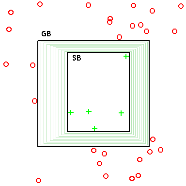
    Learning classifier systems, or LCS, are a paradigm of rule-based machine learning methods that combine a discovery component (e.g. typically a genetic algorithm in evolutionary computation) with a learning component (performing either supervised learning, reinforcement learning, or unsupervised learning). Learning classifier systems seek to identify a set of context-dependent rules that collectively store and apply knowledge in a piecewise manner in order to make predictions (e.g. behavior modeling, classification, data mining, regression, function approximation, or game strategy). This approach allows complex solution spaces to be broken up into smaller, simpler parts for the reinforcement learning that is inside artificial intelligence research. The founding concepts behind learning classifier systems came from attempts to model complex adaptive systems, using rule-based agents to form an artificial cognitive system (i.e. artificial intelligence). == Methodology == The architecture and components of a given learning classifier system can be quite variable. It is useful to think of an LCS as a machine consisting of several interacting components. Components may be added or removed, or existing components modified/exchanged to suit the demands of a given problem domain (like algorithmic building blocks) or to make the algorithm flexible enough to function in many different problem domains. As a result, the LCS paradigm can be flexibly applied to many problem domains that call for machine learning. The major divisions among LCS implementations are as follows: (1) Michigan-style architecture vs. Pittsburgh-style architecture, (2) reinforcement learning vs. supervised learning, (3) incremental learning vs. batch learning, (4) online learning vs. offline learning, (5) strength-based fitness vs. accuracy-based fitness, and (6) complete action mapping vs best action mapping. These divisions are not necessarily mutually exclusive. For example, XCS, the best known and best studied LCS algorithm, is Michigan-style, was designed for reinforcement learning but can also perform supervised learning, applies incremental learning that can be either online or offline, applies accuracy-based fitness, and seeks to generate a complete action mapping. === Elements of a generic LCS algorithm === Keeping in mind that LCS is a paradigm for genetic-based machine learning rather than a specific method, the following outlines key elements of a generic, modern (i.e. post-XCS) LCS algorithm. For simplicity let us focus on Michigan-style architecture with supervised learning. See the illustrations on the right laying out the sequential steps involved in this type of generic LCS. ==== Environment ==== The environment is the source of data upon which an LCS learns. It can be an offline, finite training dataset (characteristic of a data mining, classification, or regression problem), or an online sequential stream of live training instances. Each training instance is assumed to include some number of features (also referred to as attributes, or independent variables), and a single endpoint of interest (also referred to as the class, action, phenotype, prediction, or dependent variable). Part of LCS learning can involve feature selection, therefore not all of the features in the training data need to be informative. The set of feature values of an instance is commonly referred to as the state. For simplicity let's assume an example problem domain with Boolean/binary features and a Boolean/binary class. For Michigan-style systems, one instance from the environment is trained on each learning cycle (i.e. incremental learning). Pittsburgh-style systems perform batch learning, where rule sets are evaluated in each iteration over much or all of the training data. ==== Rule/classifier/population ==== A rule is a context dependent relationship between state values and some prediction. Rules typically take the form of an {IF:THEN} expression, (e.g. {IF 'condition' THEN 'action'}, or as a more specific example, {IF 'red' AND 'octagon' THEN 'stop-sign'}). A critical concept in LCS and rule-based machine learning alike, is that an individual rule is not in itself a model, since the rule is only applicable when its condition is satisfied. Think of a rule as a "local-model" of the solution space. Rules can be represented in many different ways to handle different data types (e.g. binary, discrete-valued, ordinal, continuous-valued). Given binary data LCS traditionally applies a ternary rule representation (i.e. rules can include either a 0, 1, or '#' for each feature in the data). The 'don't care' symbol (i.e. '#') serves as a wild card within a rule's condition allowing rules, and the system as a whole to generalize relationships between features and the target endpoint to be predicted. Consider the following rule (#1###0 ~ 1) (i.e. condition ~ action). This rule can be interpreted as: IF the second feature = 1 AND the sixth feature = 0 THEN the class prediction = 1. We would say that the second and sixth features were specified in this rule, while the others were generalized. This rule, and the corresponding prediction are only applicable to an instance when the condition of the rule is satisfied by the instance. This is more commonly referred to as matching. In Michigan-style LCS, each rule has its own fitness, as well as a number of other rule-parameters associated with it that can describe the number of copies of that rule that exist (i.e. the numerosity), the age of the rule, its accuracy, or the accuracy of its reward predictions, and other descriptive or experiential statistics. A rule along with its parameters is often referred to as a classifier. In Michigan-style systems, classifiers are contained within a population [P] that has a user defined maximum number of classifiers. Unlike most stochastic search algorithms (e.g. evolutionary algorithms), LCS populations start out empty (i.e. there is no need to randomly initialize a rule population). Classifiers will instead be initially introduced to the population with a covering mechanism. In any LCS, the trained model is a set of rules/classifiers, rather than any single rule/classifier. In Michigan-style LCS, the entire trained (and optionally, compacted) classifier population forms the prediction model. ==== Matching ==== One of the most critical and often time-consuming elements of an LCS is the matching process. The first step in an LCS learning cycle takes a single training instance from the environment and passes it to [P] where matching takes place. In step two, every rule in [P] is now compared to the training instance to see which rules match (i.e. are contextually relevant to the current instance). In step three, any matching rules are moved to a match set [M]. A rule matches a training instance if all feature values specified in the rule condition are equivalent to the corresponding feature value in the training instance. For example, assuming the training instance is (001001 ~ 0), these rules would match: (###0## ~ 0), (00###1 ~ 0), (#01001 ~ 1), but these rules would not (1##### ~ 0), (000##1 ~ 0), (#0#1#0 ~ 1). Notice that in matching, the endpoint/action specified by the rule is not taken into consideration. As a result, the match set may contain classifiers that propose conflicting actions. In the fourth step, since we are performing supervised learning, [M] is divided into a correct set [C] and an incorrect set [I]. A matching rule goes into the correct set if it proposes the correct action (based on the known action of the training instance), otherwise it goes into [I]. In reinforcement learning LCS, an action set [A] would be formed here instead, since the correct action is not known. ==== Covering ==== At this point in the learning cycle, if no classifiers made it into either [M] or [C] (as would be the case when the population starts off empty), the covering mechanism is applied (fifth step). Covering is a form of online smart population initialization. Covering randomly generates a rule that matches the current training instance (and in the case of supervised learning, that rule is also generated with the correct action. Assuming the training instance is (001001 ~ 0), covering might generate any of the following rules: (#0#0## ~ 0), (001001 ~ 0), (#010## ~ 0). Covering not only ensures that each learning cycle there is at least one correct, matching rule in [C], but that any rule initialized into the population will match at least one training instance. This prevents LCS from exploring the search space of rules that do not match any training instances. ==== Parameter updates/credit assignment/learning ==== In the sixth step, the rule parameters of any rule in [M] are updated to reflect the new experience gained from the current training instance. Depending on the LCS algorithm, a number of updates can take place at this step. For supervised learning, we can simply update the accuracy/error of a

    Read more →