AI Coding Benchmark Ranking

AI Coding Benchmark Ranking — independent reviews, comparisons, pricing and step-by-step guides on Aizhi.

  • Fantavision

    Fantavision

    Fantavision is an animation program by Scott Anderson for the Apple II and published by Broderbund in 1985. Versions were released for the Apple IIGS (1987), Amiga (1988), and MS-DOS (1988). Fantavision allows the creation of vector graphics animations using the mouse and keyboard. The user creates frames, and the software generates the frames between them. Because this is done in real-time, it allows for creative exploration and quick changes. The program uses a graphical user interface in the style of the Macintosh with pull-down menus and black text on a white background. Advertisements claimed Fantavision a revolutionary breakthrough that brings the animation features of "tweening" and "transforming" to home computers. == Reception == Compute! in 1989 called Fantavision the best animation program for the IBM PC, although it noted the inability to draw curves. == Reviews == Games #70

    Read more →
  • Automated restaurant

    Automated restaurant

    An automated restaurant or robotic restaurant is a restaurant that uses robots to do tasks such as delivering food and drink to the tables or cooking the food. Restaurant automation means the use of a restaurant management system to automate some or occasionally all of the major operations of a restaurant establishment. More recently, restaurants are opening that have completely or partially automated their services. These may include: taking orders, preparing food, serving, and billing. A few fully automated restaurants operate without any human intervention whatsoever. Robots are designed to help and sometimes replace human labour (such as waiters and chefs). The automation of restaurants may also allow for the option for greater customization of an order. == History == === Vending machines === In the late 19th and early 20th century a number of restaurants served food solely through vending machines. These restaurants were called automats or, in Japan, shokkenki. Customers ordered their food directly through the machines. === Sushi conveyors === Yoshiaki Shiraishi is a Japanese innovator who is known for the creation of conveyor belt sushi. He had the idea following difficulty staffing his small sushi restaurant and managing the restaurant on his own. He was inspired seeing beer bottles on a conveyor belt in an Asahi brewery. Yoshiaki's restaurants are an early example of restaurant automation; they used a conveyor belt to distribute dishes around the restaurant, eliminating the need for waiters. This example of automation dates back to the Japanese economic miracle; the first of Yoshiaki's conveyor belt sushi restaurants was opened under the name Mawaru Genroku Sushi in 1958, in Osaka. === Partial automation === As of 2011, across Europe, McDonald's had already begun implementing 7,000 touch screen kiosks that could handle cashiering duties. From 2015 to 2020, Zume had an automated pizza parlor. Later companies would try to produce smaller, less ambitious devices, with one robotics company producing a machine that could automate the slowest and most repetitive parts of assembling a pizza, such as spreading pizza sauce or placing slices of pepperoni, while leaving other customizations to employees. In 2020, a restaurant in the Netherlands began trialling the use of a robot to serve guests. In September 2021, Karakuri's 'Semblr' food service robot served personalised lunches for the 4,000 employees of grocery technology solutions provider ocado Group's head offices in Hatfield, UK. 2,700 different combinations of dishes were on offer. Customers could specify in grams what hot and cold items, proteins, sauces and fresh toppings they wanted. In 2021, Columbia University School of Engineering and Applied Science engineers developed a method of cooking 3D printed chicken with software-controlled robotic lasers. The “Digital Food” team exposed raw 3D printed chicken structures to both blue and infrared light. They then assessed the cooking depth, colour development, moisture retention and flavour differences of the laser-cooked 3D printed samples in comparison to stove-cooked meat. In June 2022 a California nonprofit chain of residential communities, Front Porch, experimented with robots in dining rooms at two locations to supplement wait staff by carrying plated food and drink to tables, and removing dishes. 65% of residents found the robots helpful, with 51% saying they let the staff spend more quality time with diners. 51% of staff were "excited" and 58% said they enabled more quality time with diners. The chain has 19 senior living communities (and 35 affordable housing communities), so it has potential to expand robots to more dining rooms. It is shifting to memory care, which may affect plans. == Rationales == === Advantages === Efficiency: Automated restaurants can significantly enhance operational efficiency by minimizing human error and reducing service time. With automated ordering, payment, and food preparation systems, customers can enjoy faster service and reduced waiting times. Cost savings: By reducing the need for human staff, automated restaurants can potentially lower labor costs. This can be particularly beneficial in areas with high labor expenses, as it allows for better resource allocation and cost management. Consistency: Automation ensures consistency in food quality and presentation. With precise portion control and standardized cooking methods, customers can expect the same quality and taste in their meals every time they visit. Enhanced customer experience: Self-service kiosks and automated systems provide customers with control and convenience. They can customize their orders, browse through menu options, and pay seamlessly, creating a more interactive and satisfying dining experience. === Disadvantages === Lack of personal touch: Automated restaurants may lack the personal interaction and warmth that traditional restaurants provide. Some customers prefer the human touch, personalized recommendations, and the social aspect of dining out. Technical issues: Reliance on technology means that technical glitches and malfunctions can occur, resulting in service disruptions or delays. Maintenance and technical support become critical in ensuring smooth operations. Limited menu complexity: The automation process may be better suited for standardized menu items rather than complex or customized dishes. The ability to cater to unique dietary preferences or accommodate special requests may be limited. Employment implications: Automated restaurants may result in job losses for traditional restaurant staff, potentially impacting the local workforce. It is important to consider the social and economic implications of adopting such technology. == Locations == Automated restaurants have been opening in many countries. Examples include: Nala Restaurant in Naperville, Illinois Fritz's Railroad Restaurant in Kansas City, Kansas Výtopna, a Railway Restaurant using model trains: franchise of various restaurants and coffeehouses in the Czech Republic Bagger's Restaurant in Nuremberg, Germany FuA-Men Restaurant, a ramen restaurant located in Nagoya, Japan Fōster Nutrition in Buenos Aires, Argentina Dalu Robot Restaurant in Jinan, China Haohai Robot Restaurant in Harbin, China Robot Kitchen Restaurant in Hong Kong Robo-Chef restaurant in Tehran, Iran, started in 2017, is the first robotic and "waiterless" restaurant of the Middle East. MIT graduates opened Spyce Kitchens in downtown Boston, Massachusetts, in 2018 Foodom, under Country Garden Holdings, opened January 12, 2020, in Guangzhou, China Robot Chacha, the first robot restaurant of India, is planning to open in the capital city of New Delhi. Kura Revolving Sushi Bar, with a number of locations in the United States, uses a tablets at tables for ordering, a conveyor belt to deliver food, and robots to deliver drinks and condiments. Chipotle Mexican Grill is beginning to deploy the Hyphen Makeline, which assembles up to 350 bowls and salads automatically per hour, and Chippy, an automatic tortilla chip fryer made by Miso Robotics. Serious Dumplings in Boca Raton, Florida

    Read more →
  • Rapid prototyping

    Rapid prototyping

    Rapid prototyping is a group of techniques used to quickly fabricate a scale model of a physical part or assembly using three-dimensional computer aided design (CAD) data. Construction of the part or assembly is usually done using 3D printing or "additive layer manufacturing" technology. The first methods for rapid prototyping became available in mid 1987 and were used to produce models and prototype parts. Today, they are used for a wide range of applications and are used to manufacture production-quality parts in relatively small numbers if desired without the typical unfavorable short-run economics. This economy has encouraged online service bureaus. Historical surveys of RP technology start with discussions of simulacra production techniques used by 19th-century sculptors. Some modern sculptors use the progeny technology to produce exhibitions and various objects. The ability to reproduce designs from a dataset has given rise to issues of rights, as it is now possible to interpolate volumetric data from 2D images. As with CNC subtractive methods, the computer-aided-design – computer-aided manufacturing CAD -CAM workflow in the traditional rapid prototyping process starts with the creation of geometric data, either as a 3D solid using a CAD workstation, or 2D slices using a scanning device. For rapid prototyping this data must represent a valid geometric model; namely, one whose boundary surfaces enclose a finite volume, contain no holes exposing the interior, and do not fold back on themselves. In other words, the object must have an "inside". The model is valid if for each point in 3D space the computer can determine uniquely whether that point lies inside, on, or outside the boundary surface of the model. CAD post-processors will approximate the application vendors' internal CAD geometric forms (e.g., B-splines) with a simplified mathematical form, which in turn is expressed in a specified data format which is a common feature in additive manufacturing: STL file format, a de facto standard for transferring solid geometric models to SFF machines. To obtain the necessary motion control trajectories to drive the actual SFF, rapid prototyping, 3D printing or additive manufacturing mechanism, the prepared geometric model is typically sliced into layers, and the slices are scanned into lines (producing a "2D drawing" used to generate trajectory as in CNC's toolpath), mimicking in reverse the layer-to-layer physical building process. == Application areas == Rapid prototyping is also commonly applied in software engineering to try out new business models and application architectures such as Aerospace, Automotive, Financial Services, Product development, and Healthcare. Aerospace design and industrial teams rely on prototyping in order to create new AM methodologies in the industry. Using SLA they can quickly make multiple versions of their projects in a few days and begin testing quicker. Rapid Prototyping allows designers/developers to provide an accurate idea of how the finished product will turn out before putting too much time and money into the prototype. 3D printing being used for Rapid Prototyping allows for Industrial 3D printing to take place. With this, you could have large-scale moulds to spare parts being pumped out quickly within a short period of time. == Types of Rapid Prototyping == Stereolithography (SLA) → a laser-cured photopolymer for materials such as thermoplastic-like photopolymers. Selective Laser Sintering (SLS) → a laser-sintered powder for materials such as Nylon or TPU. Direct Metal Laser Sintering (DMLS) → laser-sintered metal powder for materials like stainless steel, titanium, chrome, and aluminum. Fused Deposition Modeling (FDM) → fused extrusions of filaments like ABS, PC, and PPCU. Multi Jet Fusion (MJF) → it is an inkjet array selective fusing across bed of nylon powder for Black Nylon 12. PolyJet (PJET) → it is a uv-cured jetted photopolymer to work with acrylic-based and elastomeric photopolymers. Computer Numerical Controlled Machine (CNC) → it is used for manipulating engineering-grade thermoplastics and metals. Injection Molding (IM) → the injection is done using aluminum molds and it is used for thermoplastics, metals and liquid silicone rubber. Vacuum Casting→ is a manufacturing process used to create high-quality prototypes and small batches of parts. == History == In the 1970s, Joseph Henry Condon and others at Bell Labs developed the Unix Circuit Design System (UCDS), automating the laborious and error-prone task of manually converting drawings to fabricate circuit boards for the purposes of research and development. By the 1980s, U.S. policy makers and industrial managers were forced to take note that America's dominance in the field of machine tool manufacturing evaporated, in what was named the machine tool crisis. Numerous projects sought to counter these trends in the traditional CNC CAM area, which had begun in the US. Later when Rapid Prototyping Systems moved out of labs to be commercialized, it was recognized that developments were already international and U.S. rapid prototyping companies would not have the luxury of letting a lead slip away. The National Science Foundation was an umbrella for the National Aeronautics and Space Administration (NASA), the US Department of Energy, the US Department of Commerce NIST, the US Department of Defense, Defense Advanced Research Projects Agency (DARPA), and the Office of Naval Research coordinated studies to inform strategic planners in their deliberations. One such report was the 1997 Rapid Prototyping in Europe and Japan Panel Report in which Joseph J. Beaman founder of DTM Corporation [DTM RapidTool pictured] provides a historical perspective: The roots of rapid prototyping technology can be traced to practices in topography and photosculpture. Within TOPOGRAPHY Blanther (1892) suggested a layered method for making a mold for raised relief paper topographical maps .The process involved cutting the contour lines on a series of plates which were then stacked. Matsubara (1974) of Mitsubishi proposed a topographical process with a photo-hardening photopolymer resin to form thin layers stacked to make a casting mold. PHOTOSCULPTURE was a 19th-century technique to create exact three-dimensional replicas of objects. Most famously Francois Willeme (1860) placed 24 cameras in a circular array and simultaneously photographed an object. The silhouette of each photograph was then used to carve a replica. Morioka (1935, 1944) developed a hybrid photo sculpture and topographic process using structured light to photographically create contour lines of an object. The lines could then be developed into sheets and cut and stacked, or projected onto stock material for carving. The Munz (1956) Process reproduced a three-dimensional image of an object by selectively exposing, layer by layer, a photo emulsion on a lowering piston. After fixing, a solid transparent cylinder contains an image of the object. "The Origins of Rapid Prototyping - RP stems from the ever-growing CAD industry, more specifically, the solid modeling side of CAD. Before solid modeling was introduced in the late 1980's, three-dimensional models were created with wire frames and surfaces. But not until the development of true solid modeling could innovative processes such as RP be developed. Charles Hull, who helped found 3D Systems in 1986, developed the first RP process. This process, called stereolithography, builds objects by curing thin consecutive layers of certain ultraviolet light-sensitive liquid resins with a low-power laser. With the introduction of RP, CAD solid models could suddenly come to life". The technologies referred to as Solid Freeform Fabrication are what we recognize today as rapid prototyping, 3D printing or additive manufacturing: Swainson (1977), Schwerzel (1984) worked on polymerization of a photosensitive polymer at the intersection of two computer controlled laser beams. Ciraud (1972) considered magnetostatic or electrostatic deposition with electron beam, laser or plasma for sintered surface cladding. These were all proposed but it is unknown if working machines were built. Hideo Kodama of Nagoya Municipal Industrial Research Institute was the first to publish an account of a solid model fabricated using a photopolymer rapid prototyping system (1981). The first 3D rapid prototyping system relying on Fused Deposition Modeling (FDM) was made in April 1992 by Stratasys but the patent did not issue until June 9, 1992. Sanders Prototype, Inc introduced the first desktop inkjet 3D Printer (3DP) using an invention from August 4, 1992 (Helinski), Modelmaker 6Pro in late 1993 and then the larger industrial 3D printer, Modelmaker 2, in 1997. Z-Corp using the MIT 3DP powder binding for Direct Shell Casting (DSP) invented 1993 was introduced to the market in 1995. Even at that early date the technology was seen as having a place in manufacturing practice. A low resol

    Read more →
  • Objective vision

    Objective vision

    Objective Vision (Object Oriented Visionary) is a project mainly aimed at real-time computer vision and simulation vision of living creatures. it has three sections containing an open-source library of programming functions for using inside the projects, Virtual laboratory for scholars to check the application of functions directly and by command-line code for external and instant access, and the research section consists of paperwork and libraries to expand the scientific prove of works. == Background == The process has been used in the OVC libraries is as same as what's happening when living see a picture, and it's designed to give the researchers to experience the brain's visual cortex most close simulation for picture perception. The OVC was designed to work as a simulated visual cortex that has a critical job in processing and classify the objects to make it easier to work with pictures and graphical perception and processing. The human brain is much more aware of how it solves complex problems such as playing chess or solving algebra equations, which is why computer programmers have had so much success building machines that emulate this type of activity. but when the whole process is still a riddle that how the entities visionary system works. The project was simulated the visionary system by how it starts to convert the signals to image(actually the edges and colors) and then recognizing the shapes to find a relation between brain's information and image. The Objective Visionary system actually is concentrating on the separable sections, this separation gives the application visionary system the excellence processing result, because with this method the system do not waste much time on processing non significant sections and signals. this operation in the Objective Vision project called objective processing and because the O.V. mission is focused on human visionary simulation, so the developer refers with Objective Vision. == History == Objective-Vision is a Human (Natural) Visionary simulation Project developed by Michael Bidollahkhany. Following an explosion of interest during the 21st century were characterized by the maturing of the field and the significant growth of active applications; simulation of visionary systems, visionary based autonomous vehicle guidance, medical imaging (2D and 3D) and automatic surveillance are the most rapidly developing areas. This progress can be seen in an increasing number of software and hardware products on the market, as well as in a number of digital image processing software and APIs and also machine vision courses offered at universities worldwide. Therefore, the OVC project has been released as a research software project in 2016. One of important parts of this project was O.V.C. (Objective Vision Class library), that was designed to able companies and scientists to use the brain's most likely functionalities as visionary libraries to simplify and accelerate the image processing algorithms developments. The project started under MIT copyright license, but since 2018 the project continued as classified based on sponsors opinion. == The Algorithm == As developers claimed the algorithm used in the class library and developer's kit of project has been developed based on natural visionary system, and the functionalities containing image processing, optimization and labeling etc. are mostly upgraded and near techniques. Suppose that we've a picture of a jungle, or somewhere else, with this library developer will be able to manipulate not only the pixel of images for data extraction, but automatically based on which algorithm is used and image quality, he can manipulate directly a list of objects, same pixels and every data project needs to have, said the developer in his lecture answering how the algorithm works. === Viewpoint === For long times digital image processing and storing, was actually by processing just pixels; this Project tries to present a new kind of image processing and even storing, "objective vision" or "object-oriented visionary" is called. This project officially launched in May 2016, with the aim of making more adaptation between Computer Vision (Include Visionary, Digital image processing, discernment and even Perception) and Human Visual System; about development of the project: "...so we decided to research on Human Vision System, besides we worked on Artificial Retinal image processing and new visionary optimization unit(Presented at Istanbul Technical University Conference(Turkey 2015-2016)) and grew our research to Visionary CORTEX of Brain", Michael Bidollahkhany said. == Applications == The OVC application areas include: 2D and 3D feature toolkits Egomotion estimation Human–computer interaction (HCI) Mobile robotics Motion understanding Object identification Segmentation and recognition Stereopsis stereo vision: depth perception from two cameras Structure from motion (SFM) Motion tracking == Programming language == In first initial release of Objective Visionary Project the algorithm has been written in C++ and C#, and the virtual laboratory has been developed in C# and Delphi. Based on developers last lecture since the second release the complete algorithm has been re-written in C# based on .Net Core 1.0 to make it easier to work on different operating systems.

    Read more →
  • Azure Data Lake

    Azure Data Lake

    Azure Data Lake is a scalable data storage and analytics service. The service is hosted in Azure, Microsoft's public cloud. == History == Azure Data Lake service was released on November 16, 2016. It is based on COSMOS, which is used to store and process data for applications such as Azure, AdCenter, Bing, MSN, Skype and Windows Live. COSMOS features a SQL-like query engine called SCOPE upon which U-SQL was built. == Storage == Data Lake Storage is a cloud service to store structured, semi-structured or unstructured data produced from applications including social networks, relational data, sensors, videos, web apps, mobile or desktop devices. A single account can store trillions of files where a single file can be greater than a petabyte in size. == Analytics == Data Lake Analytics is a parallel on-demand job service. The parallel processing system is based on Microsoft Dryad. Dryad can represent arbitrary Directed Acyclic Graphs (DAGs) of computation. Data Lake Analytics provides a distributed infrastructure that can dynamically allocate resources so that customers pay for only the services they use. The system uses Apache YARN, the part of Apache Hadoop which governs resource management across clusters. Data Lake Store supports any application that uses the Hadoop Distributed File System (HDFS) interface. == U-SQL == U-SQL is a query language for Data Lake Analytics parallel data transformation and processing programs. It combines SQL and C#: it is and an evolution of the declarative SQL language with native extensibility through user code written in C#. U-SQL uses C# data types and the C# expression language. == Retirement == In 2021, Microsoft announced the 2024 retirement of the original Azure Data Lake Storage, now called "Gen1". The related Azure Data Lake Analytics / U-SQL technologies are also being retired. Azure Data Lake Storage Gen2, an extension of Azure Storage, will continue. The suggested replacement technologies are Azure Synapse Analytics and Apache Spark.

    Read more →
  • Normalization (image processing)

    Normalization (image processing)

    In image processing, normalization is a process that changes the range of pixel intensity values, a kind of intensity mapping. Applications include photographs with poor contrast due to glare, for example. A typical case is contrast stretching. In more general fields of data processing, such as digital signal processing, it is referred to as dynamic range expansion. The purpose of dynamic range expansion in the various applications is usually to bring the image, or other type of signal, into a range that is more familiar or normal to the senses, hence the term normalization. Often, the motivation is to achieve consistency in dynamic range for a set of data, signals, or images to avoid mental distraction or fatigue. For example, a newspaper will strive to make all of the images in an issue share a similar range of grayscale. Auto-normalization in image processing software typically normalizes to the full dynamic range of the number system specified in the image file format. == Definition == Normalization transforms an n-dimensional grayscale image I : { X ⊆ R n } → { Min , . . , Max } {\displaystyle I:\{\mathbb {X} \subseteq \mathbb {R} ^{n}\}\rightarrow \{{\text{Min}},..,{\text{Max}}\}} with intensity values in the range ( Min , Max ) {\displaystyle ({\text{Min}},{\text{Max}})} , into a new image I N : { X ⊆ R n } → { newMin , . . , newMax } {\displaystyle I_{N}:\{\mathbb {X} \subseteq \mathbb {R} ^{n}\}\rightarrow \{{\text{newMin}},..,{\text{newMax}}\}} with intensity values in the range ( newMin , newMax ) {\displaystyle ({\text{newMin}},{\text{newMax}})} . The linear normalization of a grayscale digital image is performed according to the formula I N = ( I − Min ) newMax − newMin Max − Min + newMin {\displaystyle I_{N}=(I-{\text{Min}}){\frac {{\text{newMax}}-{\text{newMin}}}{{\text{Max}}-{\text{Min}}}}+{\text{newMin}}} For example, if the intensity range of the image is 50 to 180 and the desired range is 0 to 255 the process entails subtracting 50 from each of pixel intensity, making the range 0 to 130. Then each pixel intensity is multiplied by 255/130, making the range 0 to 255. Normalization might also be non-linear, as the relationship between I {\displaystyle I} and I N {\displaystyle I_{N}} may not be linear. An example of non-linear normalization is when the normalization follows a sigmoid function, in which case the normalized image is computed according to the formula I N = ( newMax − newMin ) 1 1 + e − I − β α + newMin {\displaystyle I_{N}=({\text{newMax}}-{\text{newMin}}){\frac {1}{1+e^{-{\frac {I-\beta }{\alpha }}}}}+{\text{newMin}}} Where α {\displaystyle \alpha } defines the width of the input intensity range, and β {\displaystyle \beta } defines the intensity around which the range is centered. Gamma correction (log/inverse log) is also a common transformation function. === Colorspace === Intensity operations generally operate on a colorspace that maps to the human perception of lightness without intentionally changing the other properties. This can be done, for example, by operating on the L component of the CIELAB color space, or approximately by operating on the Y component of YCbCr. It is also possible to operate on each of the RGB color channels, though the result will not always make sense. == Contrast stretching == This is the most significant and essential technique of spatial-based image enhancement. The basic intent of this contrast enhancement technique is to adjust the local contrast in the image so as to bring out the clear regions or objects in the image. Low-contrast images often result from poor or non-uniform lighting conditions, a limited dynamic range of the imaging sensor, or improper settings of the lens aperture. This operation tries to change the intensity of the pixel in the image, particularly in the input image, to obtain an enhanced image. It is based on the number of techniques, namely local, global, dark and bright levels of contrast. The contrast enhancement is considered as the amount of color or gray differentiation that lies among the different features in an image. The contrast enhancement improves the quality of image by increasing the luminance difference between the foreground and background. A contrast stretching transformation can be achieved by: Stretching the dark range of input values into a wider range of output values: This involves increasing the brightness of the darker areas in the image to enhance details and improve visibility. Shifting the mid-range of input values: This involves adjusting the brightness levels of the mid-tones in the image to improve overall contrast and clarity. Compressing the bright range of input values: This process involves reducing the brightness of the brighter areas in the image to prevent overexposure resulting in a more balanced and visually appealing image. It can be described as the following piecewise funciton: I N = { s 1 r 1 I if I < r 1 s 2 − s 1 r 1 − r 2 ( I − r 1 ) if r 1 ≤ I ≤ r 2 1 − s 2 1 − r 2 ( I − r 2 ) if I > r 2 {\displaystyle I_{N}={\begin{cases}{\frac {s_{1}}{r_{1}}}I&{\text{if }}Ir_{2}\end{cases}}} Where: ( r 1 , s 1 ) {\displaystyle (r_{1},s_{1})} defines the transition point between the "dark" range to the "main" range. ( r 2 , s 2 ) {\displaystyle (r_{2},s_{2})} defines the transition point between the "main" range to the "bright" range. A typical linear stretch is obtained when ( r 1 , s 1 ) = ( r min , 0 ) {\displaystyle (r_{1},s_{1})=(r_{\text{min}},0)} and ( r 2 , s 2 ) = ( r max , 1 ) {\displaystyle (r_{2},s_{2})=(r_{\text{max}},1)} , where r min {\displaystyle r_{\text{min}}} and r max {\displaystyle r_{\text{max}}} denote the minimum and maximum levels in the source image. === Global contrast stretching === Global Contrast Stretching considers all color palate ranges at once to determine the maximum and minimum values for the entire RGB color image. This approach utilizes the combination of RGB colors to derive a single maximum and minimum value for contrast stretching across the entire image. === Local contrast stretching === Local contrast stretching (LCS) is an image enhancement method that focuses on locally adjusting each pixel's value to improve the visualization of structures within an image, particularly in both the darkest and lightest portions. It operates by utilizing sliding windows, known as kernels, which traverse the image. The central pixel within each kernel is adjusted using the following formula: I p ( x , y ) = 255 × [ I 0 ( x , y ) − m i n ] ( m a x − m i n ) {\displaystyle I_{p}(x,y)=255\times {\frac {[I_{0}(x,y)-min]}{(max-min)}}} Where: Ip(x,y) is the color level for the output pixel (x,y) after the contrast stretching process. I0(x,y) is the color level input for data pixel (x, y). max is the maximum value for color level in the input image within the selected kernel. min is the minimum value for color level in the input image within the selected kernel. A piecewise form (see above) may also be used. LCS can be applied to the three color channels of an image separately.

    Read more →
  • Corel Designer

    Corel Designer

    Corel DESIGNER is a vector-based graphics program. It was originally developed by Micrografx, which was bought by Corel in 2001. The last version developed by Micrografx was 9.0 in 2001. This program was later sold as Corel DESIGNER 9. There are still a number of users who continue working with version 9.0, because newer versions of the product are based on a modified CorelDRAW rather than the original product. Corel DESIGNER is effective for the creation of engineering drawings, but also offers many functions for graphic design. Starting with version X5, Corel DESIGNER Technical Suite includes Corel Designer, CorelDRAW and Corel Photo-Paint. X6 was the last release for Windows XP. == Release history and file formats ==

    Read more →
  • BigDog

    BigDog

    BigDog is a dynamically stable quadruped military robot platform that was created in 2005 by Boston Dynamics with the Harvard University Concord Field Station. It was funded by the U.S. Defense Advanced Research Projects Agency (DARPA), but the project was shelved after the BigDog's gas engine was deemed too loud for combat. == History == BigDog was funded by the Defense Advanced Research Projects Agency (DARPA) in the hopes that it would be able to serve as a mechanic pack mule to accompany soldiers in terrain too rough for conventional vehicles. Instead of wheels or treads, BigDog uses four legs for movement, allowing it to move across surfaces that would be difficult for wheels. The legs contain a variety of sensors, including joint position and ground contact. BigDog also features a laser gyroscope and a stereo vision system. BigDog is 3 feet (0.91 m) long, stands 2.5 feet (0.76 m) tall, and weighs 240 pounds (110 kg), making it about the size of a small mule. It is capable of traversing difficult terrain, running at four miles per hour (6.4 km/h), carrying 340 pounds (150 kg), and climbing a 35 degree incline. Locomotion is controlled by an onboard computer that receives input from the robot's various sensors. Navigation and balance are also managed by the control system. BigDog's walking pattern is controlled through four legs, each equipped with four low-friction hydraulic cylinder actuators that power the joints. BigDog's locomotion behaviors can vary greatly. It can stand up, sit down, walk with a crawling gait that lifts one leg at a time, walk with a trotting gait lifting diagonal legs, or trot with a running gait. The travel speed of BigDog varies from a 0.62 mph (1 km/h) crawl to a 3.3 mph (5.3 km/h) trot. The BigDog project was headed by Dr. Martin Buehler, who received the Joseph Engelberger Award from the Robotics Industries Association in 2012 for the work. Dr. Buehler while previously a professor at McGill University, headed the robotics lab there, developing four-legged walking and running robots. Built onto the actuators are sensors for joint position and force, and movement is ultimately controlled through an onboard computer which manages the sensors. Approximately 50 sensors are located on BigDog. These measure the attitude and acceleration of the body, motion, and force of joint actuators as well as engine speed, temperature and hydraulic pressure inside the robot's internal engine. Low-level control, such as position and force of the joints, and high-level control such as velocity and altitude during locomotion, are both controlled through the onboard computer. BigDog was featured in episodes of Web Junk 20 and Hungry Beast, and in articles in New Scientist, Popular Science, Popular Mechanics, and The Wall Street Journal. In September 2011 Boston Dynamics released video footage of a new generation of BigDog known as AlphaDog. The footage shows AlphaDog's ability to walk on rough terrain and recover its balance when kicked from the side. The refined equivalent has been designed by Boston Dynamics to exceed the BigDog in terms of capabilities and use to dismounted soldiers. In February 2012, with further DARPA support, the militarized Legged Squad Support System (LS3) variant of BigDog demonstrated its capabilities during a hike over a rough terrain. Starting in the summer of 2012, DARPA planned to complete the overall development of the system and refine its key capabilities in 18 months, ensuring its worth to dismounted warfighters before it is rolled out to squads operating in-theatre. BigDog must be able to demonstrate its ability to complete a 20-mile (32 km) trail in 24 hours, without refuelling, while carrying a 325-pound (150 kg) load. A refinement of its vision sensors will also be conducted. At the end of February 2013, Boston Dynamics released video footage of a modified BigDog with an arm. The arm could pick up objects and throw them. The robot is relying on its legs and torso to help power the motions of the arm. It is believed that it can lift weights around 55 pounds (25 kg). This work was funded by the United States Army Research Laboratory and paved the way for integrating manipulators with quadrupeds as found on Spot, the spiritual successor of BigDog. === Discontinuation === At the end of December 2013, the BigDog project was discontinued. Despite hopes that it would one day work like a pack mule for US soldiers in the field, the gasoline-powered engine was deemed too noisy for use in combat, and it could be heard from hundreds of meters away. A similar project for an all-electric robot named Spot in 2016 was much quieter, but could only carry 45 pounds (20 kg). Both projects are no longer in progress, but the Spot was only released in 2020. == Hardware == BigDog is powered by a small two-stroke, one-cylinder, 15-brake-horsepower (11 kW) engine operating at 9,000 RPM. The engine drives a hydraulic pump, which in turn drives the hydraulic leg actuators. Each leg has four actuators (two for the hip joint, and two each for the knee and ankle joints), for a total of 16. Each actuator unit consists of a hydraulic cylinder, servo valve, position sensor, and force sensor. Onboard computing power is a ruggedized PC/104 board stack with two computers, one running a Pentium M processor running QNX (used for sensor data processing) and another running a Core Duo processor (used for visual data processing). == Gallery ==

    Read more →
  • Image texture

    Image texture

    An image texture is the small-scale structure perceived on an image, based on the spatial arrangement of color or intensities. It can be quantified by a set of metrics calculated in image processing. Image texture metrics give us information about the whole image or selected regions. Image textures can be artificially created or found in natural scenes captured in an image. Image textures are one way that can be used to help in segmentation or classification of images. For more accurate segmentation the most useful features are spatial frequency and an average grey level. To analyze an image texture in computer graphics, there are two ways to approach the issue: structured approach and statistical approach. == Structured approach == A structured approach sees an image texture as a set of primitive texels in some regular or repeated pattern. This works well when analyzing artificial textures. To obtain a structured description a characterization of the spatial relationship of the texels is gathered by using Voronoi tessellation of the texels. == Statistical approach == A statistical approach sees an image texture as a quantitative measure of the arrangement of intensities in a region. In general this approach is easier to compute and is more widely used, since natural textures are made of patterns of irregular subelements. === Edge detection === The use of edge detection is to determine the number of edge pixels in a specified region, helps determine a characteristic of texture complexity. After edges have been found the direction of the edges can also be applied as a characteristic of texture and can be useful in determining patterns in the texture. These directions can be represented as an average or in a histogram. Consider a region with N pixels. the gradient-based edge detector is applied to this region by producing two outputs for each pixel p: the gradient magnitude Mag(p) and the gradient direction Dir(p). The edgeness per unit area can be defined by F e d g e n e s s = | { p | M a g ( p ) > T } | N {\displaystyle F_{edgeness}={\frac {|\{p|Mag(p)>T\}|}{N}}} for some threshold T. To include orientation with edgeness histograms for both gradient magnitude and gradient direction can be used. Hmag(R) denotes the normalized histogram of gradient magnitudes of region R, and Hdir(R) denotes the normalized histogram of gradient orientations of region R. Both are normalized according to the size NR Then F m a g , d i r = ( H m a g ( R ) , H d i r ( R ) ) {\displaystyle F_{mag,dir}=(H_{mag}(R),H_{dir}(R))} is a quantitative texture description of region R. === Co-occurrence matrices === The co-occurrence matrix captures numerical features of a texture using spatial relations of similar gray tones. Numerical features computed from the co-occurrence matrix can be used to represent, compare, and classify textures. The following are a subset of standard features derivable from a normalized co-occurrence matrix: A n g u l a r 2 n d M o m e n t = ∑ i ∑ j p [ i , j ] 2 C o n t r a s t = ∑ i = 1 N g ∑ j = 1 N g n 2 p [ i , j ] , where | i − j | = n C o r r e l a t i o n = ∑ i = 1 N g ∑ j = 1 N g ( i j ) p [ i , j ] − μ x μ y σ x σ y E n t r o p y = − ∑ i ∑ j p [ i , j ] l n ( p [ i , j ] ) {\displaystyle {\begin{aligned}Angular{\text{ }}2nd{\text{ }}Moment&=\sum _{i}\sum _{j}p[i,j]^{2}\\Contrast&=\sum _{i=1}^{Ng}\sum _{j=1}^{Ng}n^{2}p[i,j]{\text{, where }}|i-j|=n\\Correlation&={\frac {\sum _{i=1}^{Ng}\sum _{j=1}^{Ng}(ij)p[i,j]-\mu _{x}\mu _{y}}{\sigma _{x}\sigma _{y}}}\\Entropy&=-\sum _{i}\sum _{j}p[i,j]ln(p[i,j])\\\end{aligned}}} where p [ i , j ] {\displaystyle p[i,j]} is the [ i , j ] {\displaystyle [i,j]} th entry in a gray-tone spatial dependence matrix, and Ng is the number of distinct gray-levels in the quantized image. One negative aspect of the co-occurrence matrix is that the extracted features do not necessarily correspond to visual perception. It is used in dentistry for the objective evaluation of lesions [DOI: 10.1155/2020/8831161], treatment efficacy [DOI: 10.3390/ma13163614; DOI: 10.11607/jomi.5686; DOI: 10.3390/ma13173854; DOI: 10.3390/ma13132935] and bone reconstruction during healing [DOI: 10.5114/aoms.2013.33557; DOI: 10.1259/dmfr/22185098; EID: 2-s2.0-81455161223; DOI: 10.3390/ma13163649]. === Laws texture energy measures === Another approach is to use local masks to detect various types of texture features. Laws originally used four vectors representing texture features to create sixteen 2D masks from the outer products of the pairs of vectors. The four vectors and relevant features were as follows: L5 = [ +1 +4 6 +4 +1 ] (Level) E5 = [ -1 -2 0 +2 +1 ] (Edge) S5 = [ -1 0 2 0 -1 ] (Spot) R5 = [ +1 -4 6 -4 +1 ] (Ripple) To these 4, a fifth is sometimes added: W5 = [ -1 +2 0 -2 +1 ] (Wave) From Laws' 4 vectors, 16 5x5 "energy maps" are then filtered down to 9 in order to remove certain symmetric pairs. For instance, L5E5 measures vertical edge content and E5L5 measures horizontal edge content. The average of these two measures is the "edginess" of the content. The resulting 9 maps used by Laws are as follows: L5E5/E5L5 L5R5/R5L5 E5S5/S5E5 S5S5 R5R5 L5S5/S5L5 E5E5 E5R5/R5E5 S5R5/R5S5 Running each of these nine maps over an image to create a new image of the value of the origin ([2,2]) results in 9 "energy maps," or conceptually an image with each pixel associated with a vector of 9 texture attributes. === Autocorrelation and power spectrum === The autocorrelation function of an image can be used to detect repetitive patterns of textures. == Texture segmentation == The use of image texture can be used as a description for regions into segments. There are two main types of segmentation based on image texture, region based and boundary based. Though image texture is not a perfect measure for segmentation it is used along with other measures, such as color, that helps solve segmenting in image. === Region based === Attempts to group or cluster pixels based on texture properties. === Boundary based === Attempts to group or cluster pixels based on edges between pixels that come from different texture properties.

    Read more →
  • PressWise

    PressWise

    PressWise was digital imposition software to quickly and easily impose most any variety of flat and folding layouts. It was acquired by the Aldus Prepress Group affectionately known in the print and publishing industry as the Aldus WiseGuys in August 1991 from Emulation Technologies Inc. of Cleveland, Ohio. It was further developed by the Aldus Press Group and launched as the first of many Aldus prepress products in 1993. It was subsequently owned by Adobe Systems, then Luminous Corporation (Seattle), then Imation, and finally ScenicSoft. PressWise was discontinued by ScenicSoft in 1999 ultimately. == History == In February 2009, the PressWise copyright was acquired by Aethos Technologies and a new print automation product was launched by its creator, Eric Wold of Santa Rosa, California. This new product has no relationship to the old imposition software of the same name. It's notable that Larry Letteney, former President of Creo Americas was a board member and shareholder of Aethos Technologies during its early phase. Datatech SmartSoft acquired exclusive distribution rights to the software in September 2009. In September 2010 Datatech SmartSoft completed the acquisition of the PressWise brand and product.

    Read more →
  • Necrobotics

    Necrobotics

    Necrobotics is the practice of using biotic materials (or dead organisms) as robotic components. Necrobotics can serve as an alternative to mechanical components that are difficult to manufacture by using biological components designed by natural selection in order to exploit the highly developed selective design implemented in biological lifeforms via the process of evolution. In July 2022, researchers in the Preston Innovation Lab at Rice University in Houston, Texas published a paper in Advanced Science introducing the concept and demonstrating its capability by repurposing dead spiders as robotic grippers and applying pressurized air to activate their gripping arms. In April 2025 researchers at Shinshu University created a “bio-hybrid drone” using silk-worm moth antennae to detect the source of a smell. In November 2025 researchers at McGill University demonstrated the use of a mosquito proboscis as a fine nozzle in experimental 3D printing. Necrobotics utilizes the spider's organic hydraulic system and their compact legs to create an efficient and simple gripper system. The necrobotic spider gripper is capable of lifting small and light objects, thereby serving as an alternative to complex and costly small mechanical grippers. == Background == The main appeal of the spider's body in necrobotics is its compact leg mechanism and use of hydraulic pressure. The spider's anatomy utilizes a simple hydraulic (fluid) pressure system. Spider legs have flexor muscles that naturally constrict their legs when relaxed. A force is required to straighten and extend their legs, which spiders accomplish by pumping hemolymph fluid (blood) through their joints as a means of hydraulic pressure. It takes no external power to curl their legs due to their flexor muscles' natural curled state. In July 2022, researchers in the Preston Innovation Lab at Rice University published a paper detailing their experiments with the gripper. Although dead spiders no longer produce hemolymph, Te Faye Yap (lead author and mechanical engineering graduate) found that pumping air through a needle into the spider's cephalothorax (main body) accomplishes the same results as hemolymph. The original hydraulic (fluid) system is essentially converted into a pneumatic (air) system. == Fabrication == Obtain a spider Euthanize the spider using a cold temperature of around -4°C for 5-7 days Insert a 25 gauge hypodermic needle into the spider's cephalothorax (main body) Apply glue around the needle to form a seal and allow it to dry Connect a syringe or pump to the needle Extend the spider's legs by pumping air in == Testing and Data == === Internal Force Versus Gripping Force === The typical pressure in a resting spider's legs ranges from 4 kPa to 6.1 kPa. Researchers extended the legs by increasing the spider's internal pressure to 5.5 kPa. Pumping air into the body increases the internal pressure, causing the legs to expand. Pumping air out of the body decreases internal pressure, causing the legs to contract due to their flexor leg muscles. When the internal pressure decreases to 0 kPa, the gripper would be fully closed, allowing for the gripper to grasp objects. This action demonstrates that as internal pressure decreases, the gripping force increases. Inversely, when internal pressure increases, the gripping force decreases. By gripping individual weighted acetate beads, it is found that the necrobotic gripper achieves a maximum gripping force of 0.35 milinewtons. === Spider Weight Versus Gripping Force === To estimate the gripping forces of smaller and larger spiders, researchers created a plot to predict the gripping force relative to the size of the spider. The wolf spider's body weight is relatively equal to the gripping force of its legs. The mass of the gripper is 33.5 mg and can lift 1.3 times its body weight (43.6 mg or 0.35 mN). However, with larger spiders, the gripping force relative to body weight decreases. For example, a 200-gram goliath birdeater is predicted to lift 10% of its weight (20 grams or 196 mN). Though there is an inverse relationship between spider mass and gripping force, larger spiders exert greater gripping forces than smaller spiders. === Gripper Lifespan === The necrobotic gripper's functionality is entirely reliant on the structural integrity of the spider. If the spider were to break down easily and frequently, the gripper would not be practical. Using cyclic testing, a series of repeated actions, it is found that the necrobotic gripper can actuate 700 to 1000 times. After 1000 cycles, cracks begin forming on the membrane of the leg joints due to dehydration. Weakened and decomposing joints lead to frequent breakage and replacement, thereby serving as an obstacle in applying necrobotics to real-world scenarios. One theorized fix to this issue is applying beeswax or a lubricant to the joints. Researchers found that over 10 days, the mass of an uncoated spider decreased 17 times more than the mass of a spider coated with beeswax. Lubricating joints combats dehydration and slows the loss of organic material. == Constraints == With the usage of organic material, there is a higher chance of the component decomposing and breaking down as opposed to traditional mechanical systems. There may be additional work and management required to replace these grippers if they fail. Additionally, organic inconsistencies with the spiders will yield inaccurate results. Not all wolf spiders develop the same, so gripping force and leg contraction can vary between grippers. There are moral implications behind euthanizing spiders for robotics. The ethical boundaries that necrobotics push in the pursuit of biohybrid systems raise concerns, as opponents say it may lead to the hybridization of mammals and is intrusive to nature. Proponents respond that repurposing dead animals has been human practice for millennia and that necrobotics should be pursued to advance science.

    Read more →
  • Ordered dithering

    Ordered dithering

    Ordered dithering is any image dithering algorithm which uses a pre-set threshold map tiled across an image. It is commonly used to display a continuous image on a display of smaller color depth. For example, Microsoft Windows uses it in 16-color graphics modes. With the most common "Bayer" threshold map, the algorithm is characterized by noticeable crosshatch patterns in the result. == Threshold map == The algorithm reduces the number of colors by applying a threshold map M to the pixels displayed, causing some pixels to change color, depending on the distance of the original color from the available color entries in the reduced palette. The first threshold maps were designed by hand to minimise the perceptual difference between a grayscale image and its two-bit quantisation for up to a 4x4 matrix. An optimal threshold matrix is one that for any possible quantisation of color has the minimum possible texture so that the greatest impression of the underlying feature comes from the image being quantised. It can be proven that for matrices whose side length is a power of two there is an optimal threshold matrix. The map may be rotated or mirrored without affecting the effectiveness of the algorithm. This threshold map (for sides with length as power of two) is also known as a Bayer matrix or, when unscaled, an index matrix. For threshold maps whose dimensions are a power of two, the map can be generated recursively via: M 2 n = 1 ( 2 n ) 2 [ 4 M n 4 M n + 2 J n 4 M n + 3 J n 4 M n + J n ] = J 2 ⊗ M n + 1 n 2 M 2 ⊗ J n , {\displaystyle \mathbf {M} _{2n}={\frac {1}{(2n)^{2}}}{\begin{bmatrix}4\mathbf {M} _{n}&4\mathbf {M} _{n}+2\mathbf {J} _{n}\\4\mathbf {M} _{n}+3\mathbf {J} _{n}&4\mathbf {M} _{n}+\mathbf {J} _{n}\end{bmatrix}}=\mathbf {J} _{2}\otimes \mathbf {M} _{n}+{\frac {1}{n^{2}}}\mathbf {M} _{2}\otimes \mathbf {J} _{n},} where J n {\displaystyle \mathbf {J} _{n}} are n × n {\displaystyle n\times n} matrices of ones and ⊗ {\displaystyle \otimes } is the Kronecker product. While the metric for texture that Bayer proposed could be used to find optimal matrices for sizes that are not a power of two, such matrices are uncommon as no simple formula for finding them exists, and relatively small matrix sizes frequently give excellent practical results (especially when combined with other modifications to the dithering algorithm). This function can also be expressed using only bit arithmetic: M(i, j) = bit_reverse(bit_interleave(bitwise_xor(i, j), i)) / n ^ 2 == Pre-calculated threshold maps == Rather than storing the threshold map as a matrix of n {\displaystyle n} × n {\displaystyle n} integers from 0 to n 2 {\displaystyle n^{2}} , depending on the exact hardware used to perform the dithering, it may be beneficial to pre-calculate the thresholds of the map into a floating point format, rather than the traditional integer matrix format shown above. For this, the following formula can be used: Mpre(i,j) = Mint(i,j) / n^2 This generates a standard threshold matrix. for the 2×2 map: this creates the pre-calculated map: Additionally, normalizing the values to average out their sum to 0 (as done in the dithering algorithm shown below) can be done during pre-processing as well by subtracting 1⁄2 of the largest value from every value: Mpre(i,j) = Mint(i,j) / n^2 – 0.5 maxValue creating the pre-calculated map: == Algorithm == The ordered dithering algorithm renders the image normally, but for each pixel, it offsets its color value with a corresponding value from the threshold map according to its location, causing the pixel's value to be quantized to a different color if it exceeds the threshold. For most dithering purposes, it is sufficient to simply add the threshold value to every pixel (without performing normalization by subtracting 1⁄2), or equivalently, to compare the pixel's value to the threshold: if the brightness value of a pixel is less than the number in the corresponding cell of the matrix, plot that pixel black, otherwise, plot it white. This lack of normalization slightly increases the average brightness of the image, and causes almost-white pixels to not be dithered. This is not a problem when using a gray scale palette (or any palette where the relative color distances are (nearly) constant), and it is often even desired, since the human eye perceives differences in darker colors more accurately than lighter ones, however, it produces incorrect results especially when using a small or arbitrary palette, so proper normalization should be preferred. In other words, the algorithm performs the following transformation on each color c of every pixel: c ′ = n e a r e s t _ p a l e t t e _ c o l o r ( c + r × ( M ( x mod n , y mod n ) − 1 / 2 ) ) {\displaystyle c'=\mathrm {nearest\_palette\_color} {\mathopen {}}\left(c+r\times \left(M(x{\bmod {n}},y{\bmod {n}})-1/2\right){\mathclose {}}\right)} where M(i, j) is the threshold map on the i-th row and j-th column, c′ is the transformed color, and r is the amount of spread in color space. Assuming an RGB palette with 23N evenly distanced colors where each color (a triple of red, green and blue values) is represented by an octet from 0 to 255, one would typically choose r ≈ 255 N {\textstyle r\approx {\frac {255}{N}}} . (1⁄2 is again the normalizing term.) Because the algorithm operates on single pixels and has no conditional statements, it is very fast and suitable for real-time transformations. Additionally, because the location of the dithering patterns always stays the same relative to the display frame, it is less prone to jitter than error-diffusion methods, making it suitable for animations. Because the patterns are more repetitive than error-diffusion method, an image with ordered dithering compresses better. Ordered dithering is more suitable for line-art graphics as it will result in straighter lines and fewer anomalies. The values read from the threshold map should preferably scale into the same range as the minimal difference between distinct colors in the target palette. Equivalently, the size of the map selected should be equal to or larger than the ratio of source colors to target colors. For example, when quantizing a 24 bpp image to 15 bpp (256 colors per channel to 32 colors per channel), the smallest map one would choose would be 4×2, for the ratio of 8 (256:32). This allows expressing each distinct tone of the input with different dithering patterns. === A variable palette: pattern dithering === == Non-Bayer approaches == The above thresholding matrix approach describes the Bayer family of ordered dithering algorithms. A number of other algorithms are also known; they generally involve changes in the threshold matrix, which changes the distribution of the "noise" introduced by all kinds of dithering (the difference between the original image and the dithered image). === Halftone === Halftone dithering performs a form of clustered dithering, creating a look similar to halftone patterns, using a specially crafted matrix. === Void and cluster === The Void and cluster algorithm uses a pre-generated blue noise as the matrix for the dithering process. The blue noise matrix keeps the Bayer's good high frequency content, but with a more uniform coverage of all the frequencies involved shows a much lower amount of patterning. The "voids-and-cluster" method gets its name from the matrix generation procedure, where a black image with randomly initialized white pixels is gaussian-blurred to find the brightest and darkest parts, corresponding to voids and clusters. After a few swaps have evenly distributed the bright and dark parts, the pixels are numbered by importance. It takes significant computational resources to generate the blue noise matrix: on a modern computer a 64×64 matrix requires a couple seconds using the original algorithm. This algorithm can be extended to make animated dither masks which also consider the axis of time. This is done by running the algorithm in three dimensions and using a kernel which is a product of a two-dimensional gaussian kernel on the XY plane, and a one-dimensional Gaussian kernel on the Z axis. === Simulated Annealing === Simulated annealing can generate dither masks by starting with a flat histogram and swapping values to optimize a loss function. The loss function controls the spectral properties of the mask, allowing it to make blue noise or noise patterns meant to be filtered by specific filters. The algorithm can also be extended over time for animated dither masks with chosen temporal properties.

    Read more →
  • Joox

    Joox

    Joox (stylised in all caps) is a music streaming service owned by Tencent, launched in January 2015. Joox is the biggest music streaming app in Asian markets such as Hong Kong, Macau, Indonesia, Malaysia, Myanmar, Thailand and also in South Africa before it was shut down in early 2022. Joox is a freemium service, providing most of its songs free, while some songs are only available for premium users, offered via paid subscriptions or by doing different tasks offered. In 2017, Joox launched their service in their first non-Asian market, South Africa, which for an unknown reason shut down five years later. The service now accounts for more than 50% of all music streaming app downloads in their Asian markets. The number of music-streaming users in Hong Kong, Macau, Malaysia, Thailand, Myanmar and Indonesia was expected to reach 87 million by 2020. == Background == Before the emergence of Joox, Tencent owned QQ Music, one of the largest music streaming and download service in China. In 2015, they introduced Joox as their expansion of music services to overseas market instead of mainland China, starting first in Hong Kong. Instead of providing free services by playing audio ads to users like Spotify, another major music service, Joox focused on banner ads, splash ads and other advertising methods such as category playlists and in-app skins. They claimed it as a success. Joox offered their premium VIP access to DStv subscribers free of charge. DStv is the sister company to Tencent and is the primary pay-TV provider in South Africa. In November 2021, it was announced that Joox will stop streaming in South Africa in March 2022.

    Read more →
  • Human–robot collaboration

    Human–robot collaboration

    Human-Robot Collaboration is the study of collaborative processes in human and robot agents work together to achieve shared goals. Many new applications for robots require them to work alongside people as capable members of human-robot teams. These include robots for homes, hospitals, and offices, space exploration and manufacturing. Human-Robot Collaboration (HRC) is an interdisciplinary research area comprising classical robotics, human-computer interaction, artificial intelligence, process design, layout planning, ergonomics, cognitive sciences, and psychology. Industrial applications of human-robot collaboration involve Collaborative Robots, or cobots, that physically interact with humans in a shared workspace to complete tasks such as collaborative manipulation or object handovers. == Collaborative Activity == Collaboration is defined as a special type of coordinated activity, one in which two or more agents work jointly with each other, together performing a task or carrying out the activities needed to satisfy a shared goal. The process typically involves shared plans, shared norms and mutually beneficial interactions. Although collaboration and cooperation are often used interchangeably, collaboration differs from cooperation as it involves a shared goal and joint action where the success of both parties depend on each other. For effective human-robot collaboration, it is imperative that the robot is capable of understanding and interpreting several communication mechanisms similar to the mechanisms involved in human-human interaction. The robot must also communicate its own set of intents and goals to establish and maintain a set of shared beliefs and to coordinate its actions to execute the shared plan. In addition, all team members demonstrate commitment to doing their own part, to the others doing theirs, and to the success of the overall task. == Theories Informing Human-Robot Collaboration == Human-human collaborative activities are studied in depth in order to identify the characteristics that enable humans to successfully work together. These activity models usually aim to understand how people work together in teams, how they form intentions and achieve a joint goal. Theories on collaboration inform human-robot collaboration research to develop efficient and fluent collaborative agents. === Belief Desire Intention Model === The belief-desire-intention (BDI) model is a model of human practical reasoning that was originally developed by Michael Bratman. The approach is used in intelligent agents research to describe and model intelligent agents. The BDI model is characterized by the implementation of an agent's beliefs (the knowledge of the world, state of the world), desires (the objective to accomplish, desired end state) and intentions (the course of actions currently under execution to achieve the desire of the agent) in order to deliberate their decision-making processes. BDI agents are able to deliberate about plans, select plans and execute plans. === Shared Cooperative Activity === Shared Cooperative Activity defines certain prerequisites for an activity to be considered shared and cooperative: mutual responsiveness, commitment to the joint activity and commitment to mutual support. An example case to illustrate these concepts would be a collaborative activity where agents are moving a table out the door, mutual responsiveness ensures that movements of the agents are synchronized; a commitment to the joint activity reassures each team member that the other will not at some point drop his side; and a commitment to mutual support deals with possible breakdowns due to one team member's inability to perform part of the plan. === Joint Intention Theory === Joint Intention Theory proposes that for joint action to emerge, team members must communicate to maintain a set of shared beliefs and to coordinate their actions towards the shared plan. In collaborative work, agents should be able to count on the commitment of other members, therefore each agent should inform the others when they reach the conclusion that a goal is achievable, impossible, or irrelevant. == Approaches to Human-Robot Collaboration == The approaches to human-robot collaboration include human emulation (HE) and human complementary (HC) approaches. Although these approaches have differences, there are research efforts to develop a unified approach stemming from potential convergences such as Collaborative Control. === Human Emulation === The human emulation approach aims to enable computers to act like humans or have human-like abilities in order to collaborate with humans. It focuses on developing formal models of human-human collaboration and applying these models to human-computer collaboration. In this approach, humans are viewed as rational agents who form and execute plans for achieving their goals and infer other people's plans. Agents are required to infer the goals and plans of other agents, and collaborative behavior consists of helping other agents to achieve their goals. === Human Complementary === The human complementary approach seeks to improve human-computer interaction by making the computer a more intelligent partner that complements and collaborates with humans. The premise is that the computer and humans have fundamentally asymmetric abilities. Therefore, researchers invent interaction paradigms that divide responsibility between human users and computer systems by assigning distinct roles that exploit the strengths and overcome the weaknesses of both partners. == Key Aspects == Specialization of Roles: Based on the level of autonomy and intervention, there are several human-robot relationships including master-slave, supervisor–subordinate, partner–partner, teacher–learner and fully autonomous robot. In addition to these roles, homotopy (a weighting function that allows a continuous change between leader and follower behaviors) was introduced as a flexible role distribution. Establishing shared goal(s): Through direct discussion about goals or inference from statements and actions, agents must determine the shared goals they are trying to achieve. Allocation of Responsibility and Coordination: Agents must decide how to achieve their goals, determine what actions will be done by each agent, and how to coordinate the actions of individual agents and integrate their results. Shared context: Agents must be able to track progress toward their goals. They must keep track of what has been achieved and what remains to be done. They must evaluate the effects of actions and determine whether an acceptable solution has been achieved. Communication: Any collaboration requires communication to define goals, negotiate over how to proceed and who will do what, and evaluate progress and results. Adaptation and learning: Collaboration over time require partners to adapt themselves to each other and learn from one's partner both directly or indirectly. Time and space: The time-space taxonomy divides human-robot interaction into four categories based on whether the humans and robots are using computing systems at the same time (synchronous) or different times (asynchronous) and while in the same place (collocated) or in different places (non-collocated). Ergonomics: Human factors and ergonomics are one of the key aspects for a sustainable human-robot collaboration. The robot control system can use biomechanical models and sensors to optimize various ergonomic metrics, such as muscle fatigue.

    Read more →
  • Macromedia FreeHand

    Macromedia FreeHand

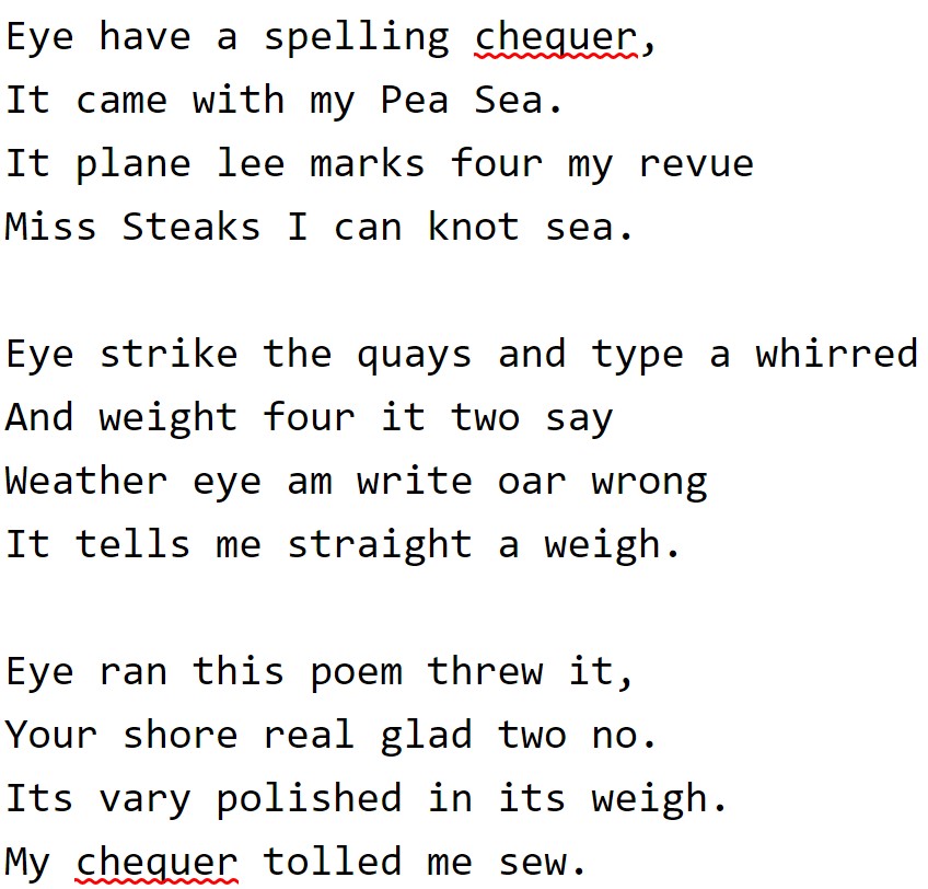
    Macromedia FreeHand (formerly Aldus FreeHand) is a discontinued computer application for creating two-dimensional vector graphics oriented primarily to professional illustration, desktop publishing and content creation for the Web. FreeHand was similar in scope, intended market, and functionality to Adobe Illustrator, CorelDRAW and Xara Designer Pro. Because of FreeHand's dedicated page layout and text control features, it also compares to Adobe InDesign and QuarkXPress. Professions using FreeHand include graphic design, illustration, cartography, fashion and textile design, product design, architects, scientific research, and multimedia production. FreeHand was created by Altsys Corporation in 1988 and licensed to Aldus Corporation, which released versions 1 through 4. In 1994, Aldus merged with Adobe Systems and because of the overlapping market with Adobe Illustrator, FreeHand was returned to Altsys by order of the Federal Trade Commission. Altsys was later bought by Macromedia, which released FreeHand versions 5 through 11 (FreeHand MX). In 2005, Adobe Systems acquired Macromedia and its product line which included FreeHand MX, under whose ownership it presently resides. Since 2003, FreeHand development has been discontinued; in the Adobe Systems catalog, FreeHand has been replaced by Adobe Illustrator. FreeHand MX continues to run under Windows 11 and under Mac OS X 10.6 (Snow Leopard) within Rosetta, a PowerPC code emulator, and requires a registration patch supplied by Adobe. FreeHand 10 runs without problems on Mac OS X Snow Leopard with Rosetta enabled, and does not require a registration patch. Later versions of macOS can use a Mac OS X Snow Leopard Server virtual machine to emulate the required PowerPC support. == History == === Altsys and Aldus FreeHand === In 1984, James R. Von Ehr founded Altsys Corporation to develop graphics applications for personal computers. Based in Plano, Texas, the company initially produced font editing and conversion software; Fontastic Plus, Metamorphosis, and the Art Importer. Their premier PostScript font-design package, Fontographer, was released in 1986 and was the first such program on the market. With the PostScript background having been established by Fontographer, Altsys also developed FreeHand (originally called Masterpiece) as a Macintosh Postscript-based illustration program that used Bézier curves for drawing and was similar to Adobe Illustrator. FreeHand was announced as "... a Macintosh graphics program described as having all the features of Adobe's Illustrator plus drawing tools such as those in Mac Paint and Mac Draft and special effects similar to those in Cricket Draw." Seattle's Aldus Corporation acquired a licensing agreement with Altsys Corporation to release FreeHand along with their flagship product, Pagemaker, and Aldus FreeHand 1.0 was released in 1988. FreeHand's product name used intercaps; the F and H were capitalized. The partnership between the two companies continued with Altsys developing FreeHand and with Aldus controlling marketing and sales. After 1988, a competitive exchange between Aldus FreeHand and Adobe Illustrator ensued on the Macintosh platform with each software advancing new tools, achieving better speed, and matching significant features. Windows PC development also allowed Illustrator 2 (aka, Illustrator 88 on the Mac) and FreeHand 3 to release Windows versions to the graphics market. FreeHand 1.0 sold for $495 in 1988. It included the standard drawing tools and features as other draw programs including special effects in fills and screens, text manipulation tools, and full support for CMYK color printing. It was also possible to create and insert PostScript routines anywhere within the program. FreeHand performed in preview mode instead of keyline mode but performance was slower. FreeHand 2.0 sold for $495 in 1989. Besides improving on the features of FreeHand 1.0, FreeHand 2 added faster operation, Pantone colors, stroked text, flexible fill patterns and automatically import graphic assets from other programs. It added accurate control over a color monitor screen display, limited only by its resolution. FreeHand 3.0 sold for $595 in 1991. New features included resizable color, style, and layer panels including an Attributes menu. Also tighter precision of both the existing tools and aligning of objects. FH3 created compound Paths. Text could be converted to paths, applied to an ellipse, or made vertical. Carried over from version 1.0, FreeHand 3 suffered by having text entered into a dialog box instead of directly to the page. In October 1991, a 3.1 upgrade made FreeHand work with System 7 but additionally, it supported pressure-sensitive drawing which offered varying line widths with a users stroke. It improved element manipulation and added more import/export options. FreeHand 4.0 sold for $595 in 1994. Altsys ported FreeHand 3.0 to the NeXT system creating a new program named Virtuoso. Virtuoso continued its development at Altsys and version 2.0 of Virtuoso was feature-equivalent to FreeHand 4 (with the addition of NeXT-specific features such as Services and Display PostScript) and file compatible, with Virtuoso 2 able to open FreeHand 4 files and vice versa. A prominent feature of this version was the ability to type directly into the page and wrap inside or outside any shape. It also included drag-and-drop color imaging, a larger pasteboard, and a user interface that featured floating, rollup panels. The colors palette included a color mixer for adding new colors to the swatch list. Speed increases were made. In the same year of FreeHand 4 release, Adobe Systems announced merger plans with Aldus Corporation for $525 million. Fear about the end of competition between these two leading applications was reported in the media and expressed by customers (Illustrator versus FreeHand and Adobe Photoshop versus Aldus PhotoStyler.) Because of this overlapping of the market, Altsys stepped in by suing Aldus, saying that the merger deal was "a prima facie violation of a non-compete clause within the FreeHand licensing agreement." Altsys CEO Jim Von Ehr explained, "No one loves FreeHand more than we do. We will do whatever it takes to see it survive." The Federal Trade Commission issued a complaint against Adobe Systems on October 18, 1994, ordering a divestiture of FreeHand to "remedy the lessening of competition resulting from the acquisition as alleged in the Commission's complaint," and further, the FTC ordering, "That for a period of ten (10) years from the date on which this order becomes final, respondents shall not, without the prior approval of the Commission, directly or indirectly, through subsidiaries, partnerships, or otherwise .. Acquire any Professional Illustration Software or acquire or enter into any exclusive license to Professional Illustration Software;" (referring to FreeHand.) FreeHand was returned to Altsys with all licensing and marketing rights as well as Aldus FreeHand's customer list. === Macromedia Freehand === By late 1994, Altsys still retained all rights to FreeHand. Despite brief plans to keep it in-house to sell it along with Fontographer and Virtuoso, Altsys reached an agreement with the multimedia software company, Macromedia, to be acquired. This mutual agreement provided FreeHand and Fontographer a new home with ample resources for marketing, sales, and competition against the newly merged Adobe-Aldus company. Altsys would remain in Richardson, Texas, but would be renamed as the Digital Arts Group of Macromedia and was responsible for the continued development of FreeHand. Macromedia received FreeHand's 200,000 customers and expanded its traditional product line of multimedia graphics software to illustration and design graphics software. CEO James Von Ehr became a Macromedia vice-president until 1997 when he left to start another venture. FreeHand 5.0 sold for $595 in 1995. This version featured a more customizable and expanded workspace, multiple views, stronger design and editing tools, a report generator, spell check, paragraph styles, multicolor gradient fills up to 64 colors, speed improvements, and it accepted Illustrator plugins. In September 1995, a 5.5 upgrade added Photoshop plug-in support, PDF import capabilities, the Extract feature, inline graphics to text, improved auto-expanding text containers, the Crop feature, and the Create PICT Image feature. A FreeHand 5.5 upgrade was part of the FreeHand Graphics Studio (a suite that included Fontographer, Macromedia xRes image editing application, and Extreme 3D animation and modeling application). FreeHand 6.0 in 1996. This version only existed in beta. Some Freehand 7 prerelease versions were released under the Freehand 6 tag. FreeHand 7.0 sold for $399 in 1996, or $449 as part of the FreeHand Graphics Studio (see above.) Features included a redesigned user interface that allowed recombining Inspectors, Panel Tabs, Dockable Panels, Smart Cursors,

    Read more →